Unsupported Bridge Test & Principle Explanation


Print Profile(3)


Description
Principle (Based on G-code with S ≈ 0.378 mm)
Parameters (from this file):
Nozzle = 0.40 mm Bridge line width w = 0.42 mm Layer height h = 0.20 mm Base cross-section A0 = w*h = 0.084 mm² Measured bridge line spacing S ≈ 0.378 mm
Why default flow (1.0) sags:
- In standard layers, the nozzle squishes filament, and about 15% overlap ensures adjacent lines fuse well.
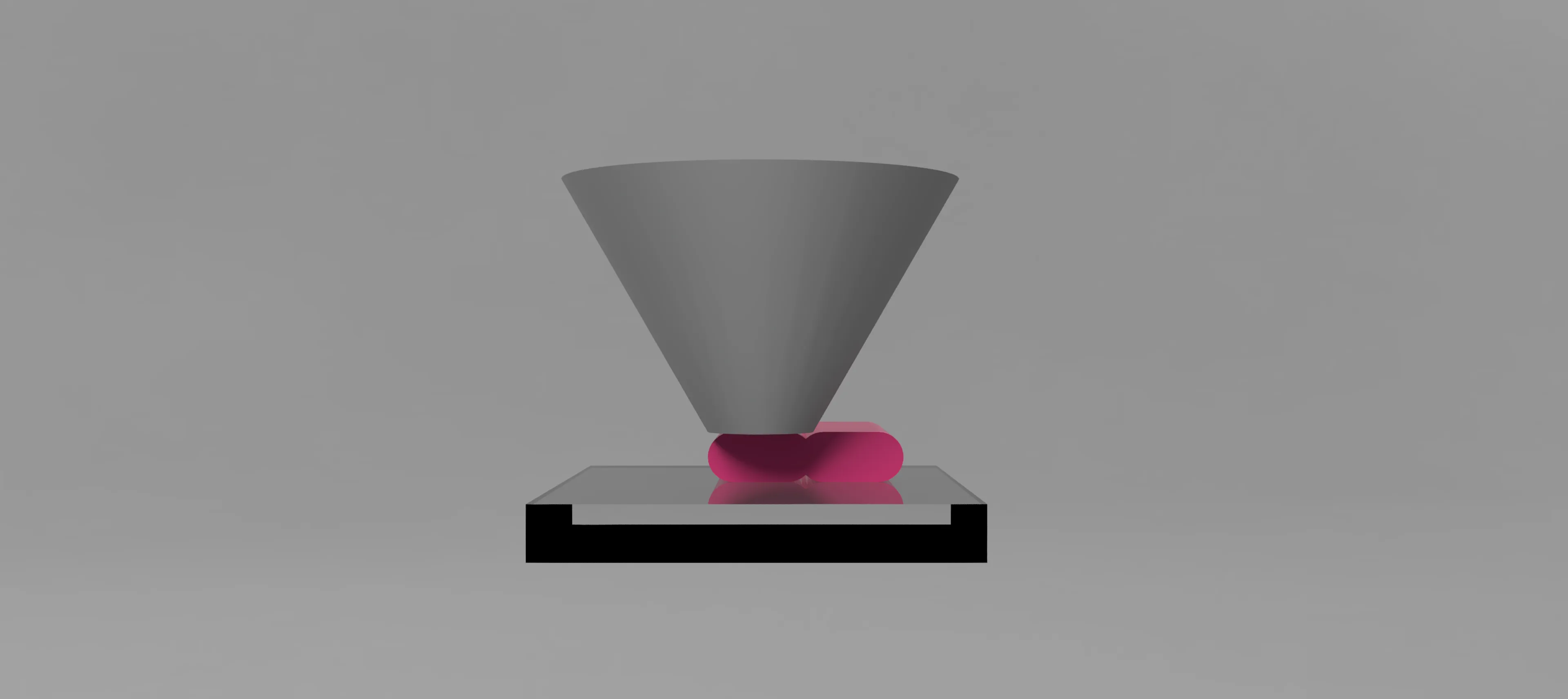
During bridging, the filament is airborne and round, so at default flow its diameter is only:
d ≈ sqrt((4*A0)/π) ≈ 0.327 mm
This is smaller than the spacing (0.378 mm), so the lines can’t touch, causing sagging.
Normal Printing 
Bridge Printing 
Bridge Printing with Adjusted Flow
Flow rate calculation:
We want d ≈ S:
d ≈ sqrt((4*m*A0)/π) Let d = S = 0.378 => m ≈ (π*S²) / (4*A0) => m ≈ 1.336 (theoretical “just touching”)
Practical recommendation:
Real-world printing needs margin for airflow, vibration, and cooling effects.
Set bridge flow to 1.45–1.60× for a stable, clean bridge.
Even though your slicer uses ~10% overlap (spacing 0.378 mm), aiming slightly higher than the theoretical 1.33× ensures consistent adhesion and avoids weak spots.
Comment & Rating (22)