electrical box / puszka kartongips DUAL


Print Profile(1)

Description
Ramka (puszka) elektryczna, do ściany z kartongipsu, gdy nie potrzeba (lub nie chcemy) mieć tylnej części puszki, by mieć np pełny dostęp do przestrzeni za ścianą (np do umieszczenia tam elektroniki smart home)
Wymiarowana pod typowy europejski standard osprzętu 60mm (odstęp puszek 72mm). Osprzęt (gniazdko, włącznik itp) przykręca się standardowymi wkrętami osprzętowymi W16. Przód z tyłem puszki skręca się wkrętami M3 z łbem stożkowym DIN 7991 (imbus) lub DIN965 (philips) o długości 16mm (co najmniej), z ewentualnymi nakrętkami M3 z tyłu (lub wprost wkręt w plastik puszki)
Puszka składa się z 2 części - tylną wkładamy przez otwór (podwójny) od tyłu w kartongips, i “wyciągamy do siebie” na wcisk w gips, bo dodatkowo posiada ona ząbki klinujące w gipsie. Potem przykładamy przednią część, i skręcamy (przynajmniej na 4, ale lepiej na 8 szt) wkrętów M3
ENG:
Electrical frame (box), for plasterboard od drywall walls, when you don't need (or don't want) the back of the box to have full access to the space behind the wall (e.g. to place smart home electronics there).
Size for the typical European 60mm fixture standard (72mm box spacing). Electric devices (socket, switch, etc.) are secured with standard W16 fixture screws.
The front and back of the box are secured with M3 countersunk DIN 7991 (Allen) or DIN 965 (Philips) screws, with optional M3 nuts at the back (or a screw directly into the plastic of the box).
The box consists of two parts – the rear parts you should place through an existing hole in the wall. Then, press into the plasterboard from the back, using a press fit. Rear part have teeth for wedge-shaped fixings.
Then, the front part is placed and screwed in place (using at least four, but preferably eight) with M3 screws.
- TURN POWER DOWN ! (and double check, if there is no live wires!)
- Un-install your existing equipment :

- Remove old wall-box

- Cut it in pieces (if you do not want to re-wire equipment)
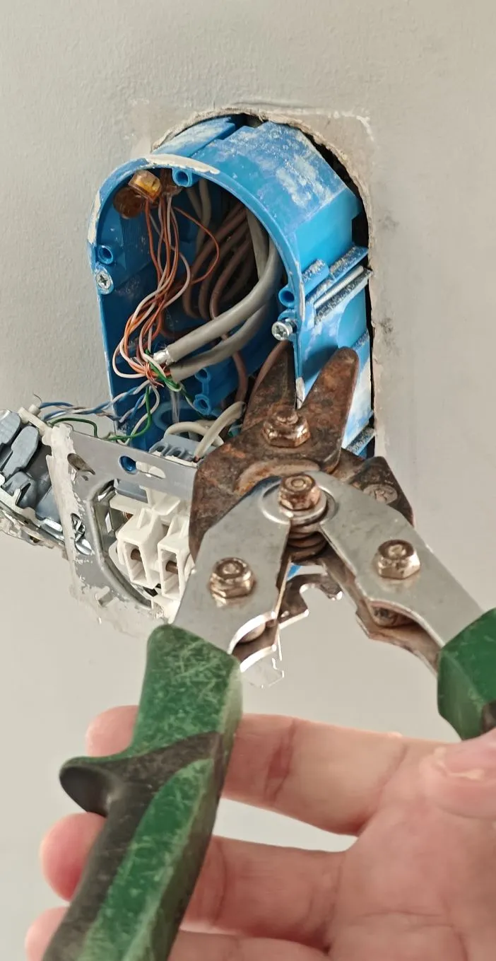
Now You have clean hole, you can put BOTTOM part inside:

- Pass the accessories through the new LOWER frame (if it passes through it, if not - you need to disconnect the wires, pass the wires themselves and connect them again)

- Put the LOWER (BOTTOM) frame in hole, angled a little, and push it inside

- Once the frame is completely behind the board, straighten it and pull it forward so that it fits into the hole from the back.

- Insert the hardware with cables through the TOP part of the frame and screw it to the BOTTOM part

- Now you can add smart modules to the cavity inside of the wall …
- …and when you're finished, screw the hardware back into the new frame.

Done!
Comment & Rating (0)