OpenHD Ground Station - Raspberry PI - BLM8812EU


Print Profile(1)

Description
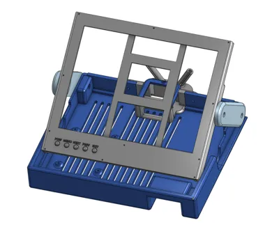
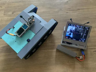
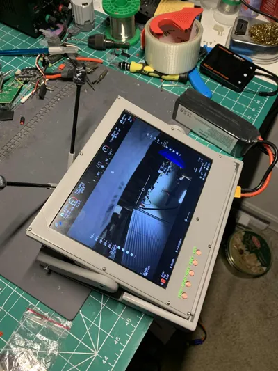
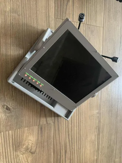
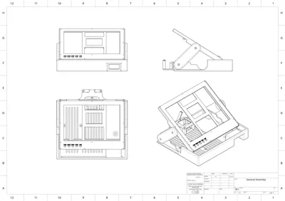
OpenHD Ground Station design using Rapberry PI and the BLM8812EU Wifi Adapter.
It has been tested successfully with a Raspberry PI Zero 2W.
For any reference on the software please visit OpenHD
BOM:
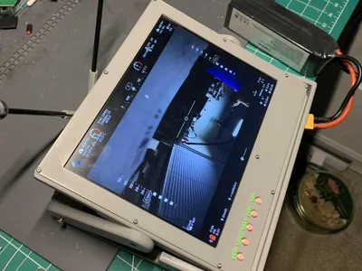
- 1 x Pimoroni HDMI 8" IPS LCD Screen Kit - 1024x768
- 1 x BL-M8812EU2 Long Range Unmanned Aerial Vehicle 5G High Power Wifi Module
- 1 x Mini HDMI to HDMI Coiled Cable
- 1 x Raspberry PI Zero WH
- 2 x HGLRC LHCP Long Range Antenna FPV Hammer 2.5dBi Mini 5.8G
- 1 x LM2596 DC to DC High Efficiency Voltage Regulator 3.2-35V to 1.25-30V Buck Converter
- 1 x FPV UBEC Micro 5V 3A / 12V 2A UBEC
- 1 x 2Pcs Pure Copper Heatsink 1.18" x 1.18" x 0.28"
- 1 x 3007 Fan Black for Raspberry Pi 4 Fan 30x30x7mm
- 2 x Micro USB Male Type B 5 Terminal Jack Port Solder Connector
- 1 x Short Micro USB Cable
- Cables: 2PIN Female and Male Connecting Plug with Red Black Terminal Connector
- 1 x XT60 Power connector, female
- 6 x M3 20mm screws + nuts
- 4 x M3 6mm screws
- 8 x M2 10mm screws
- 3 x M2 5mm screws
- 3 x M2.5 10 screws
Skills:
- soldering small pins, notion of electronics to prevent shorts and polarity inversions.
Notes:
- For the USB cable from the Raspberry PI to the adapter, I recommend to sacrifice a micro USB cable to prevent mistakes, cut it at the desired size, open it along 4-5 cm length to strip the internal wires from the external envelop. Solder the wires (D+/D-/Gnd) on the Wifi adapter, check the specifications for the correct pins.
- For the Raspberry Pi power, the cables can be used with their connectors (USB-mini to JST Male/Female), this would help isolating the different electronic parts of the build.
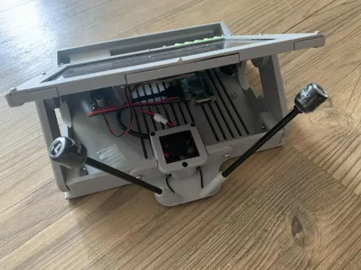
- The Heatsink needs to be stuck to the Wifi adapter component and it will slide in the adapter box, on top of that you can add the fan to dissipate some heat. Solder the fan on the adapter pins to make the radio module standalone.
- The Wifi module needs to be plugged to the FPV UBEC module to get an independent source of power. I soldered the FPV UBEC directly to the buck converter input voltage, with a cable. Then took the output of the FPV UBEC and connected it to the Wifi Adapter. Check the Wifi adapter specifications to get the correct pins diagrams.
- Both the screen and the raspberry pi need to be powered through micro-usb cable, just take the header and solder them on a wire that will go to the output of the Buck converter. Before powering your station, verify that the buck converter output 5V and not more.
Comment & Rating (0)