QLG2 GNSS Enclosure + LED Solder Jig (Rev 2 PCB)


Print Profile(2)

Bill of Materials


Description
Boost Me (for free)
If this precision-engineered design saved you time or improved your shack, please consider a Boost! Your support helps me fund the hardware and filament needed to develop and test more FreeCAD solutions for the Ham Radio community.
Thank You! 73 AD9FA
QRP Labs - QLG2 GNSS
Part of the LogicLayerDesign High-Precision Radio Series.
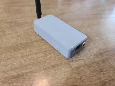
This is a compact enclosure designed for the QRP Labs QLG2 GNSS Receiver Rev 2 PCB. If you have a different board revision and would like a modified version, please leave a comment! It allows space for the optional Ultra-cap (super capacitor) and uses a 3.5mm headphone jack for connection to other QRP Labs kits. I have included print profiles that accommodate external LEDs and also print profiles that do not use external LEDs. I have also included ones with a GPS satellite graphic and ones with no graphic that you can leave one solid color or decorate it yourself. You will also find a print profile for a LED install guide / jig that you can print that will help you align the LEDs perfectly saving a lot of time and frustration getting them just right. This guide print will make getting the LEDs soldered in the perfect position easy and ensure that your GNSS will just slip into the enclosure when finished. The jig will not only align the LEDs perfectly but also set them to 1.4mm above the case making them easy to see from any angle. I strongly suggest that you take advantage of this install jig. Its only a few cents in material to print but will possibly save you hours in frustration. Directions on using the LED install guide can be found below.
If you find this useful please share the love and like and boost. It helps me be able to keep designing. Thank you in advance!
Parts Needed
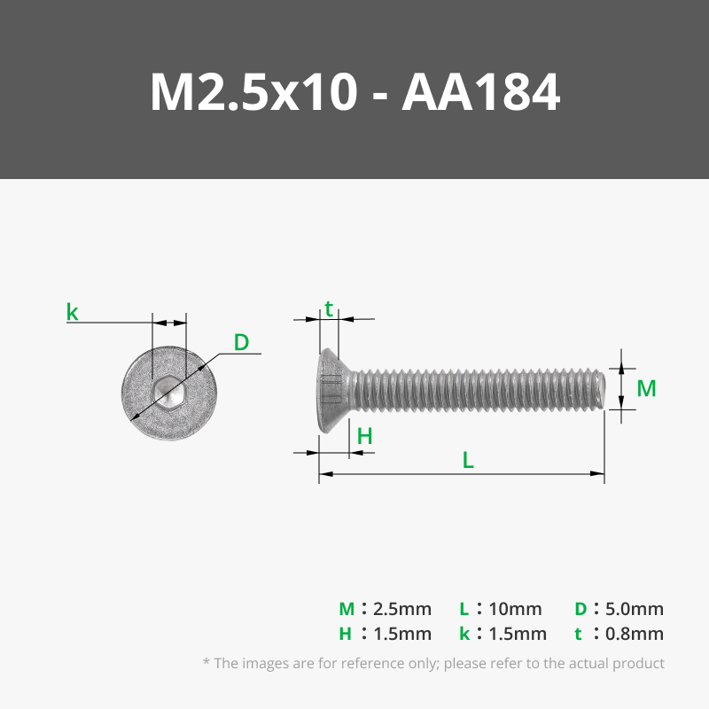
- You will need four M2.5x8 or M2.5x10 screws for the case. Maker supply link below.
2. You will also need a 3.5mm panel mount stereo jack. Optional parts include LEDs (Red, Yellow, and Green), small Antenna, and a 0.47f Ultra-cap. I bought these from DigiKey.com.
The following are links to the parts I used. I have seen similar 3.5mm stereo jacks on Amazon but after reading the reviews I decided to get all parts from DigiKey.com
PARTS:
OPTIONAL:
How To Print The GPS Satellite Graphic
There are two ways to get the GPS Satellite graphic to print.
The first way is to click the “Objects” tab in the “Process” menu. Then find “GPS_3mm.stl” in the list. There is one for each plate. Right click the GPS-3mm.stl and in the pop-up menu go to “Change Filament” and select a different color than the base color. The Graphic for that plate will now print in the color you have chosen. See pic below as an example.

The second way is to use the “Color Painting” tool in the tool bar at the top. Select one of the “Case Tops” and Press the letter “N” on your keyboard or left click the “Color Painting” tool found in the tool bar at the top of the view window. A configuration window will appear. At the very top of the paint configuration window you will select a color to paint the graphic. Just under that section will be “Tool Type”. Select the one that looks like a Bucket called “Fill”. When selected two radial buttons will appear under the “Tool Type” section. Select the “Edge Detection” radial. Now rotate the part (In this case it will be the “Case Top”) so you can see the bottom of the part. Now you can hover over the part and see the different parts of the graphic get highlighted. Just click each piece of the graphic to paint them the selected color. Using this method will allow you to color different parts of the graphic different colors. Have fun with it and personalize it to your liking. An example of the “Color Painting” tool and settings can be seen in the pic below.

LED Install Guide Instructions
The first step is to print the LED install guide and get all your supplies together.

The next step is to insert the LEDs into the proper holes in the PCB. Please be sure to insert the LEDs in the proper orientation. The cathodes (negative - short lead) goes towards the center of the PCB. The Anodes (positive - longer lead) goes towards the edge of the board. The order from the left to the right is. Red. Yellow. Green.

Insert the GNSS into the top housing of the guide as shown below.

Now put the bottom cover on and screw it down. You now have everything held together so you can adjust the LED leads so each color is fully inserted into the top holes in the guide. Be sure not to make a bend in the leads too close to the PCB. Adjust each led until it is more or less floating in its position allowing for a slight up and down movement. This ensures that the LED is at the proper angle to the hole and that the guide can adjust the overall height of the LEDs before soldering.

Now that you have the LEDs all ready its time to get ready to solder. Place the guide, LED side down, flat on a table or other flat work surface. Do not do this step on any kind of soft or pliable surface. Make sure the guide is sitting flat against the table and not held up by any of the LEDs. If it will not sit flat on its own without holding it down please revisit the last step. Now just make sure that each LED is inserted all the way to the work surface (without causing the guide to lift off the work surface) and solder each lead and cut off the excess lead when done. That's it. Your QLG2 is now ready to be removed from the guide.

Assembly Instructions
Please refer to the QLG2 manual available on the QRP LABs website for wiring the 3.5 mm stereo jack.
https://qrp-labs.com/images/qlg2/manual_1_00a.pdf
Push the stereo jack through the hole on the case cover and secure with the included round nut.

Place the QLG2 into the cover as shown in the picture below.

Insert the bottom cover and secure with four M2.5x8 or M2.5x10 screws.

Congratulations! Your QLG2 is now secure inside the case ready for use.

Thank You!
73,
AD9FA
Boost Me (for free)
If this precision-engineered design saved you time or improved your shack, please consider a Boost! Your support helps me fund the hardware and filament needed to develop and test more FreeCAD solutions for the Ham Radio community.
Thank You! 73 AD9FA
Parts Needed
- You will need four M2.5x8 or M2.5x10 screws for the case. Maker supply link below.
2. You will also need a 3.5mm panel mount stereo jack. Optional parts include LEDs (Red, Yellow, and Green), small Antenna, and a 0.47f Ultra-cap. I bought these from DigiKey.com.
The following are links to the parts I used. I have seen similar 3.5mm stereo jacks on Amazon but after reading the reviews I decided to get all parts from DigiKey.com
PARTS:
OPTIONAL:
License
You shall not share, sub-license, sell, rent, host, transfer, or distribute in any way the digital or 3D printed versions of this object, nor any other derivative work of this object in its digital or physical format (including - but not limited to - remixes of this object, and hosting on other digital platforms). The objects may not be used without permission in any way whatsoever in which you charge money, or collect fees.
Comment & Rating (12)