
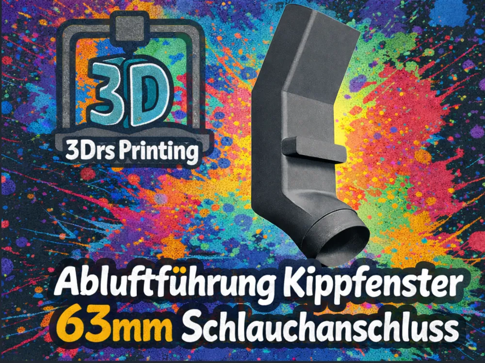
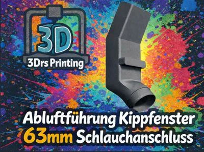
Tilt Window Exhaust Air Ducting 63mm Hose Connection V2
Print Profile(5)




Description
Dimensions and Measurements
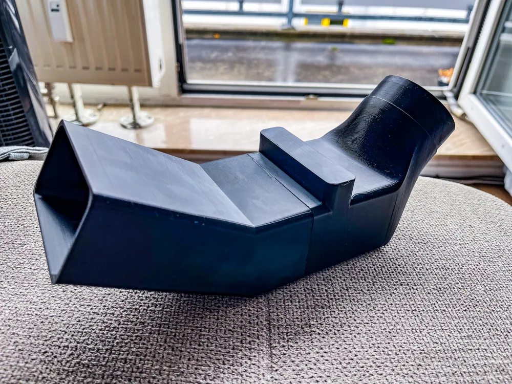
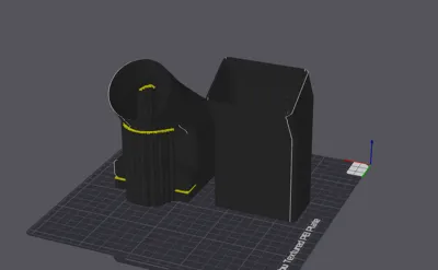
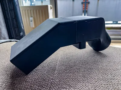
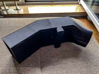
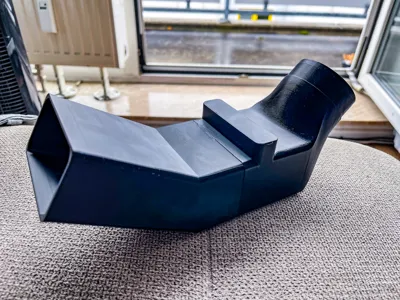
The model consists of two interlocking parts with an overall compact volume The outer dimensions are approximately **84 mm width × 109 mm depth × 142 mm height** (X × Y × Z) The connection nozzle at the hose end has an **outer diameter of 63 mm**, suitable for standard flexible exhaust hoses The **base plate** (window support) is approximately triangular in shape and measures roughly **78 mm** (width) × **49 mm** (depth) in plan view; it connects directly to the window frame The wall thickness of the housing is on average 2–3 mm (depending on the chosen print profile and number of perimeters)
Function and Use Case
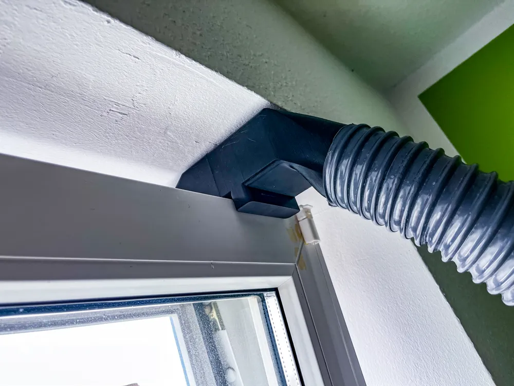
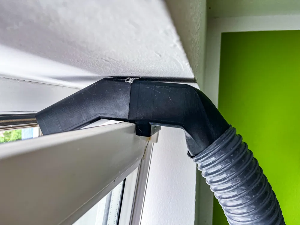
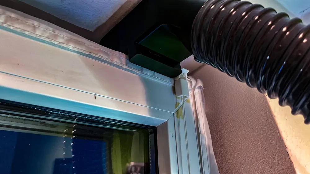
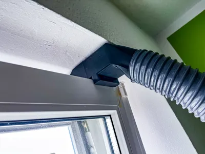
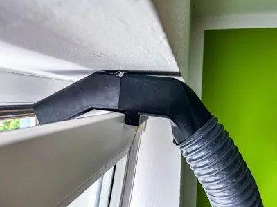
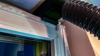
This exhaust duct directs warm or contaminated air from a room to the outside without having to fully open the window It is specifically designed for **tilted windows** (e.g. skylights or tilt windows) The round drilled hose end connects a 63 mm exhaust hose to the duct The duct is pushed into the diagonally opened window rebate so that the warm exhaust air is “perfectly discharged through an open window” Then you close the window (tilt position) again, so that the part clamps firmly and seals In this way, for example, with mobile air conditioners, laser cutters, or 3D printers, exhaust heat or smoke/odor can be efficiently led outside, while the room temperature is largely maintained
Construction and Geometry
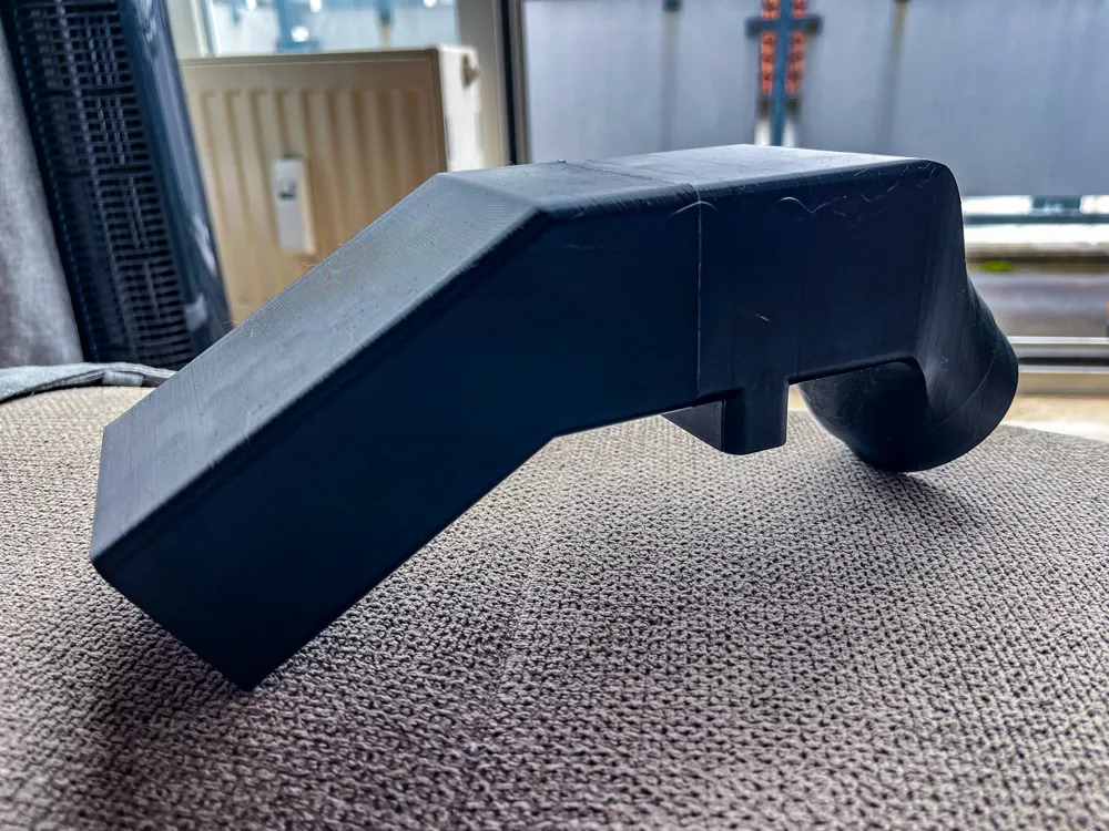
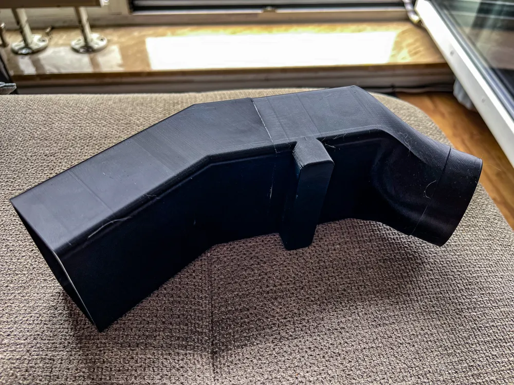
The air duct is designed at an **angle**: the hose connection is on the narrow side, the duct itself leads diagonally upwards or sideways out The base plate is **triangular** so that it can be clamped into a narrow window rebate At the top, the duct tapers towards the round hose connection The bottom side of the duct (the window slide rail) is flat and rectangular, which facilitates sealing with window sealant or sealing tape The model has additional rib structures or reinforcing edges at critical points to increase stability when clamped For assembly, snap-in mechanisms (e.g. a twist-lock standard) are integrated at the inner end, with which compatible hose modules can be snapped in Recommended sealing is done by applying **window sealant** or cellular rubber to the edge
Material Recommendation
Due to the relatively hot exhaust air (typically 40–60 °C), the part should be printed from heat-resistant filament **PLA** is less suitable due to its low glass transition range (approx 55 °C), as deformation threatens Materials such as **PETG**, **ASA**, or **ABS** are better These have higher heat resistance (PETG ≈ 70 °C, ABS ≈ 98 °C) and are more durable PETG also offers good chemical and weather resistance as well as better layer adhesion A model description explicitly recommends PETG (or ASA/ABS) instead of PLA because “the exhaust air can get warm” For temporary use in home or workshop environments (e.g. with air conditioners), ASA is equally well suited, as it is similarly heat-resistant to ABS and additionally more UV-resistant In summary: **PETG** (or ASA/ABS) is recommended because these plastics withstand hot exhaust air and off-gas less
Print Settings
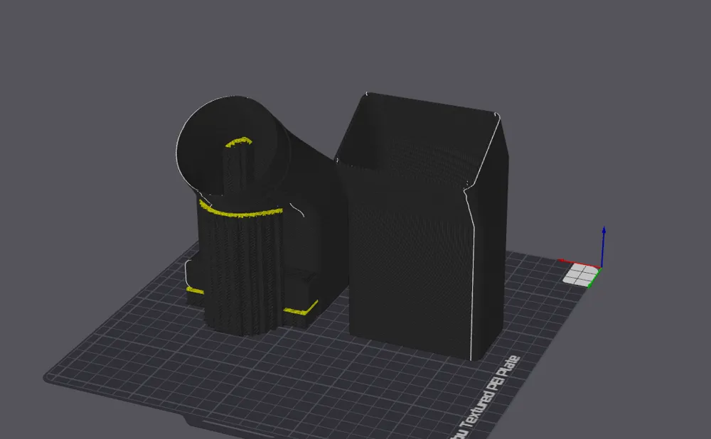
For good stability, typically **3 perimeters** are printed and a **layer height of 0.2 mm** is chosen Infill of 15–20% is usually sufficient Generally, one can adhere to common print profiles: e.g. 0.2 mm layer height, 3 perimeters and ~15–20% infill When printing – depending on the printer – a **0.4 mm nozzle** (standard), bed temperature around 60–70 °C (for PETG), and nozzle temperature according to filament specifications (e.g. 230–250 °C for PETG) is recommended A **brim** can improve adhesion, especially with ABS/ASA The duct has comparatively mild overhangs
License



Comment & Rating (8)