Search models, users, collections, and posts

Sim Rig Roll Cage Roof

Print Profile(3)

All
P1P
H2D
X1E
A1
X1
P1S
H2D Pro
X1 Carbon
H2S
P2S
H2C
X2D
A2L

0.2mm layer, 2 walls, 15% infill
Designer
10.2 h
3 plates
5.0(8)

0.2mm layer, 2 walls, 8% infill Fixed wrong size for 1 part
11 h
3 plates

0.2mm layer, 2 walls, 10% infill 40mm PVC from big greenshed
13.8 h
3 plates

Open in Bambu Studio
Boost
189
555
41
14
303
119
Released 

Description

Heavily inspired by the similar model on Thingiverse (https://www.thingiverse.com/thing:6543667).  This version allows for the more common 60 degree angle of monitors (original model designed for 53 degree angle) and 40mm pipes, which are cheap and easily obtained in most DIY stores.


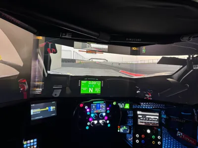
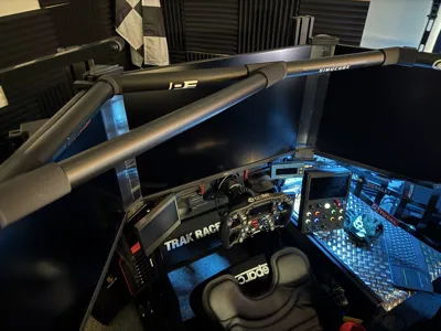
The assembled frame is lightweight and simply sits on top of your monitors.  It won't move unintentionally, but can easily be lifted if needed for access.  If you have a 4th monitor or need more height, take a look at Jasons WIP model - https://makerworld.com/en/models/1655359-wip-sim-roof


To create this, you will need;


3x A2 Foam Boards (or 2x A1, if you can find them). 

2x 2m lengths of 40mm push-fit waste pipe (I used black, but white would give a more ‘roll cage’ feel)

(optional, but recommended) 100x150cm fabric to cover (this is sufficient to cover the side visible in the rig - you will need more to cover the top) I recommend spray adhesive to fix


Steps;


  1. Print parts - I printed in PLA with 15% infill, which is sufficient and lightweight
  2. Cut Pipe to length (I highly recommend a pipe cutter for ease and a straight clean but, but a hacksaw will do the job).  For 32" monitors you will need the following lengths - 170mm, 2x 300mm, 515mm, 310mm & 370mm. These sizes are approximate, so if you're cutting all pieces before assembly, I strongly recommend cutting slightly longer then trimming to fit during assembly. 2 lengths of pipe will leave you enough ‘waste’.
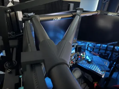
  3. Assemble the frame and test fit over your monitors
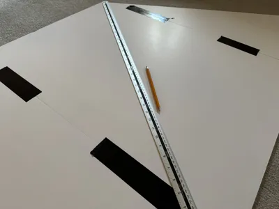
  4. Join the foam boards - I used strong duct tape
  5. Place the frame on top of the foam boards
  6. Cut the joined foam boards - this will be the sides cut to an angle.  Allow some overlap. Do another test fit
  7. Cover the final foam boards
  8. Assemble & enjoy!
  9. Optional - the assembled boards will simply sit on top of the frame quite happily without needing to be fixed, however you could use either hot glue or adhesive velcro to connect the frame and boards if you wish

Comment & Rating (41)

(0/1000)

Print Profile
0.2mm layer, 2 walls, 15% infill
I used 1.5”larger pipe and had to scale the print but worked great.
(Edited)
profile
2
Reply
Do happen to have the re scale file for 1.5" pipe?
(Edited)
0
Reply
Replying to @user_320499534 :
I will double check on PC what % I scaled them to next time I’m there! send me a DM on here so I remember.
0
Reply
Replying to @Kazob :
Thanks.
0
Reply
Rescaled my print and used 40mm pipe from the Australian big green shed. Couldn't find the pipe in the original post. I hot glued all my pieces together. I can also repost my print if others need it. Thanks Legend!
designer
4
Reply
Do you happen to have the file for a 40 mm tube? I would like to make it with 40 mm as well
Show original
1
Reply
Boosted
If you could upload your file that would be great thanks, I'm the same as you only have access to the big green shed.
1
Reply
I'll boot up my PC tomorrow and add the remix! sorry fellas 😅
0
Reply
i have added a profile that fixes the wrong scaled part and some other small fixes to make the print nicer.
The designer has replied
designer
2
Reply
legend! 🤘🏻
0
Reply
Thank you! Appreciate the effort
0
Reply
Awesome print mate! I'm just curious though did anyone else have the issue where the parts don't seem to be scaled correctly? not sure if it's me printing off my phone with bambu handy but even the print plate images don't look scaled correctly? cheers
2
Reply
Printing mine right now, currently on the third plate and just noticed this myself. What did you do to correct it?
1
Reply
Replying to @user_1903611572 :
I haven't gotten around to fixing it and to be honest I don't think I can be bothered haha. I'm just gonna glue everything together and see how it looks. worst case I'll use the desktop computer app to resize it so that it matches the biggest size correctly as it seems to fit really nicely with the pipe
1
Reply
Printed mine, cut the pipes, and have it mocked up on the floor. But I have a question. From the few pictures posted, it looks like the corner left piece is at a harder angle than the piece I printed. The middle Y fitting looks like it would be just above and in front of the drivers head. Mine looks like it'll be running adjacent to the center monitor. Is this correct? My monitors aren't exactly at 60° but probably off by 1-2 degrees. On another note, during mock up, instead of using glue I wrapped some duct tape about one and a half times around the connections of the printed pieces. This snuggly holds the pipes in place. I might just keep it that way but will resort to gluing if it doesn't hold in the long run. Thank you to the creator of this cage.
The designer has replied
0
Reply
Looks like you’ve connected the bits slightly wrong - you shouldn’t have a long piece in front of the centre monitor, as it looks like you have there. Check the photos posted by myself and Bozak above. if you have the correct pipe, no glue or tape should be needed, but thats personal preference
1
Reply
Replying to @GripFuel :
I've repeatedly looked at both those sets of pics. Honestly, it's hard to tell which length pipe goes where. I ended up putting it on my rig for a test fit and the front pipe doesn't run adjacent to my center monitor as I thought it would. I think it might help out a lot if you could include a diagram of where each pipe goes. I think the angle of your pictures makes it a little hard to tell where each length is supposed to go. I used PVC pipe. I think you're from across the pond and not sure if waste pipe is what you call it. But mine doesn't have a tight fit. It'll fall right out. The tape definitely holds it in place but already decided I'm gonna glue it cuz the whole thing sags a little bit with the tape. But thanks again for your design and your response. Happy racing!
0
Reply
Print Profile
0.2mm layer, 2 walls, 15% infill
really awesome print. minor issue with the bambu handy file. on the second plate, the larger part is too large of a diameter for 1.25" schedule 40. all other parts are perfect. Will scale down and reprint.
(Edited)
1
Reply
Isn't getting in and out quite inconvenient Ideally, it could fold up 🤔 Otherwise, very nice work 👍🏼
The designer has replied
Show original
0
Reply
It’s not as easy, but equally not too difficult. It’s light enough to lift a bit at the front if you need to (and the ‘lips’ on the edges prevent it from falling on you)
1
Reply
Boosted
Getting into a real GT3 is not exactly an S-Class either
Show original
1
Reply
Replying to @North_G4 :
Correct, but since it's not a GT3, I've now designed it to be foldable 😉
Show original
0
Reply
@GripFuel any chance you can help getting this thing on 65 angled triples?
The designer has replied
0
Reply
Take a look at the remix posted by @just_actual_kev - https://makerworld.com/en/models/2162098-simrig-rollcage-70-degree-and-60-degree-and-roof#profileId-2344163 He's recreated it and provided the STEP files which I think may be parametric (mine sadly wasn't)
0
Reply
Replying to @GripFuel :
thanks dude I'll look into it!
0
Reply
Oh great Even in the file the models are scaled differently While the smaller parts are at 132% the actually larger part is at 100% Does anyone here have a quick fix for this Very unpleasant that the files are not correct which I only now see after 10 hours of printing
The designer has replied
Show original
1
Reply
I will check the file tomorrow and re-upload if needed. The file uploaded is the one I used to print my own, and the scaling is fine on that - perhaps a bambu app update has done something
0
Reply
Hey, is there a reason that the diameter of the connectors is different? One part fro example has adiameter of 37mm, while the others have 33mm?
2
Reply