Gridfinity Electronic Component Storage, Arduino


Print Profile(1)

Description
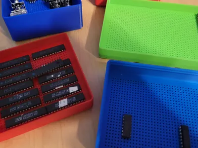
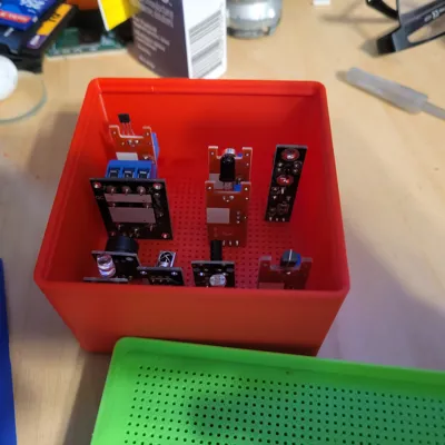
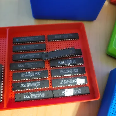
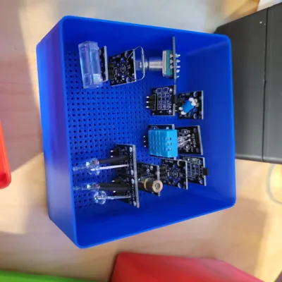
I have a bunch of discrete logic, old microprocessors and Aurdino parts laying around in different parts bins. I wanted something that was standard were I could stack them and store them. I had seen others, but this had a stacking component.
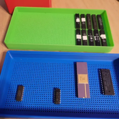
So I built the bins similar to https://makerworld.com/en/models/234549-gridfinity-esp32-1x2-bin?from=search#profileId-493143, which uses square holes, I used round. This is standard industry component spacing of 2.54mm on center, and I used 1.1mm holes.
I also wanted to store them in this https://makerworld.com/en/models/1103813-modern-gridfinity-case?from=search#profileId-1099318. So I designed the trays to stack 3 high in the 12U case.
Based on the Gridfinity spec, a 1U space is 7mm, I used the bottom 3mm to build the grid, allowing 3mm leads. But because of lip, it adds an additional 4.4mm to the case. Because of that standard 4U with lip would not allow me to store 3 high. So I played around with the parameters, and created bins within 1mm of the standard with Lip, that is why you may see a file that says 3.4u, which is 1mm shy of the 4U. The .m3f
Note: a new parametric version is available, it fixes some issues, like sitting in bins, need of supports, etc. Check it out (https://makerworld.com/en/models/2236358-parametric-gridfinity-electronic-component-holder#profileId-2433738).
I hope people can use them.
Also if you have a specific requirement size wise, reach out and I can generate a new size, I have an openSCAD generate to do this.
One last note, you MUST use supports to print this. The bottom will not come out correctly with out them. But depending on the length of the legs of the components, you may or may not need to remove the supports. Also the support are a bit of a pain to remove, so if someone has an idea of how I could use less supports, I am open to suggestions.

Comment & Rating (18)