
2U 10 Inch Rackmount Mini-ITX + Flex ATX Enclosure
Print Profile(1)

Description
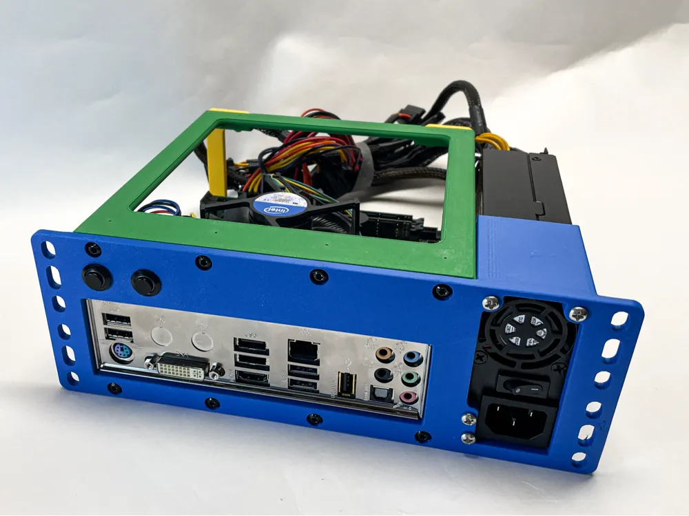
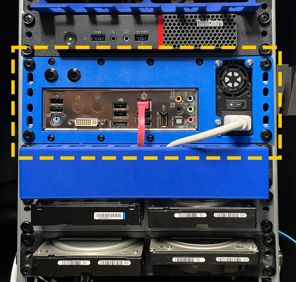
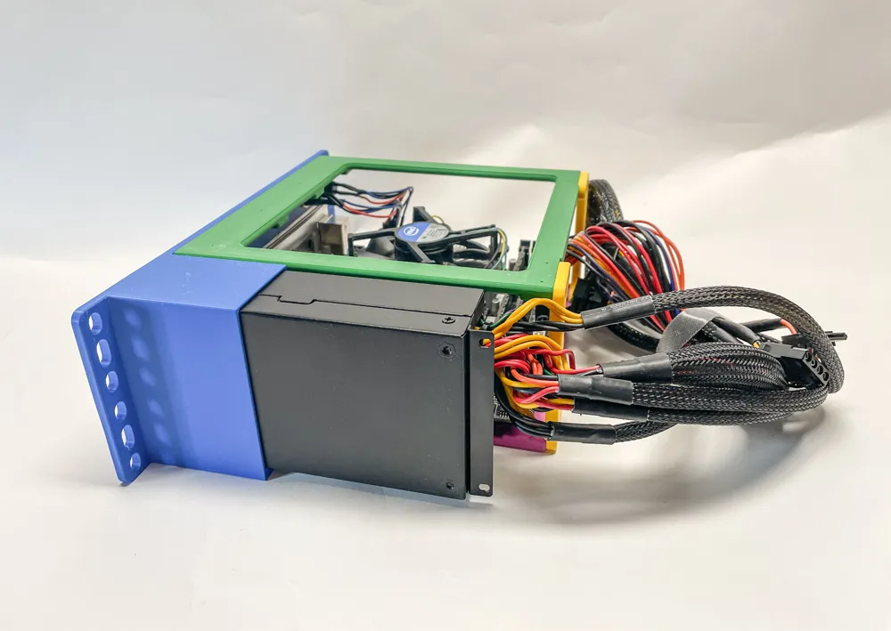
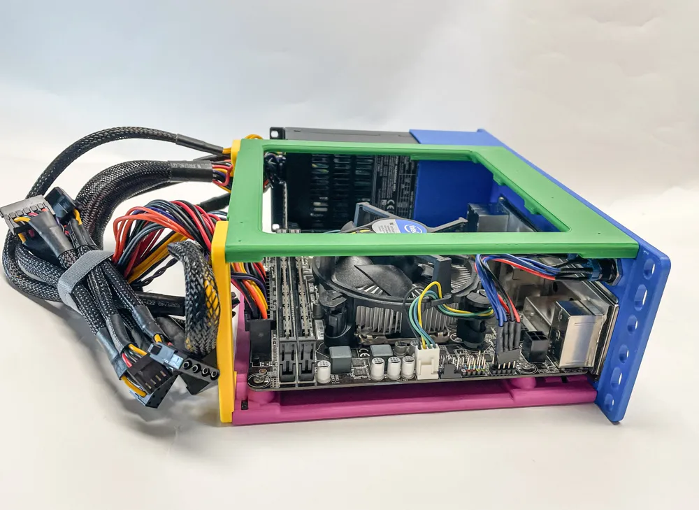
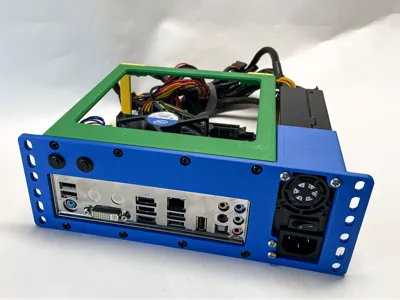
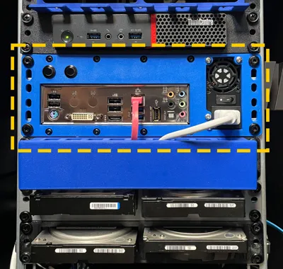
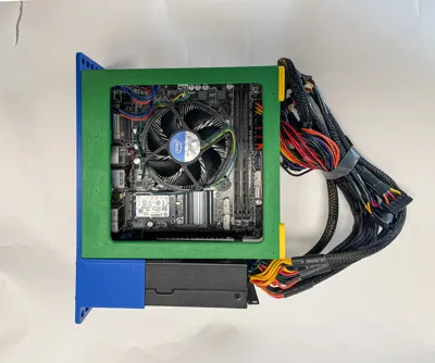
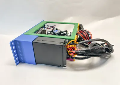
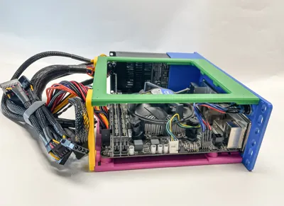
very compact 2U 10 Inch Rackmount Mini-ITX + Flex ATX Enclosure
very easy to print and assemble - assembly instructions see below
Unfortunately, I only have limited test hardware available. Let me know if anything doesn't fit properly, and I'll try to make the necessary adjustments.
Required parts:
PLA Filament from Extrudr, Bambu,…. (I think brand doesn't matter)
Screws:
8 x M4 x 20mm
8 x M4 x 10mm
4 x M3 x 6mm for Mainboard
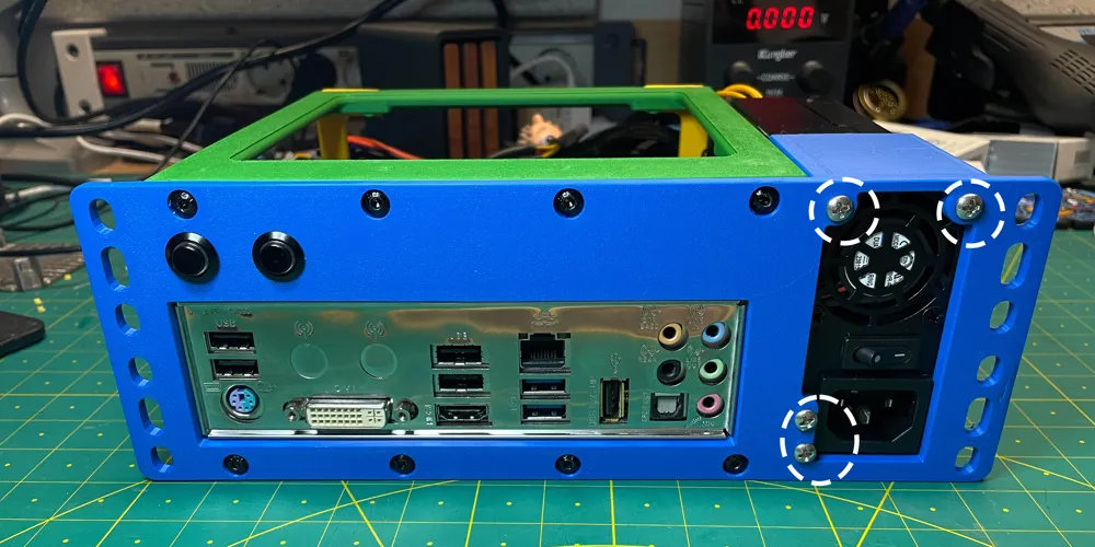
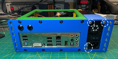
4 x UNC 6-32 3/8 for Flex ATX PSU
Nuts:
16 x M4
Inserts:
4 x M3 inserts
I used this screws and nuts:
M4: https://www.amazon.de/dp/B0CPXFG3TW
UNC: https://www.amazon.de/dp/B087D61D5X
Buttons:
I used these for the power and reset buttons. ==> https://www.amazon.de/dp/B0DBKCGZVB
However, any standard 12mm panel buttons can be used.
You have to adjust the pins accordingly for your mainboard.
Update 24.08.2025: added Front for 16mm buttons
Hardware I used:
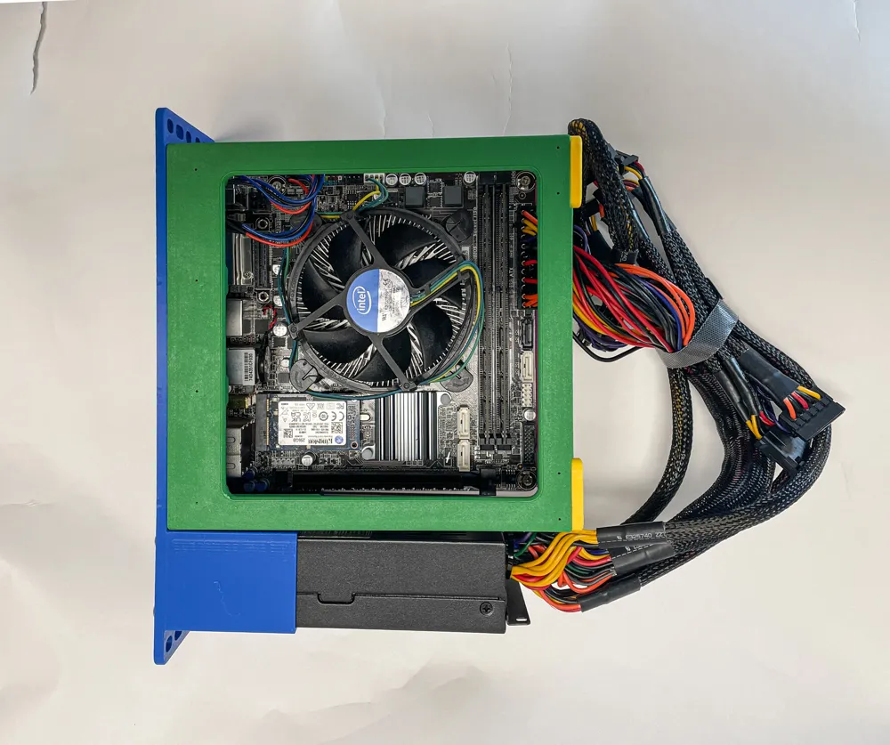
Power supply: SilverStone SST-FX350-G - Flex Serie or Fortron Flexguru 300W ==> modulare PSU would be a good choice, as you don't need all the cables.
Mainboard: Mini-ITX mainboard from old PC, any Mini-ITX mainboard should fit. You might have to be careful with the cooler to make sure you don't exceed the 2U.
Please note: This is a 10-inch DIY case. You'll need some basic PC knowledge to build it, as it involves installing power-carrying components (mainboard and power supply). So be careful! You are responsible for your safety.
Boost Me (for free)
I create the models in my free time and attach great importance to their precision and ease of manufacture.
If you like it, I'd appreciate a boost. THANK YOU!
Assembly instructions:
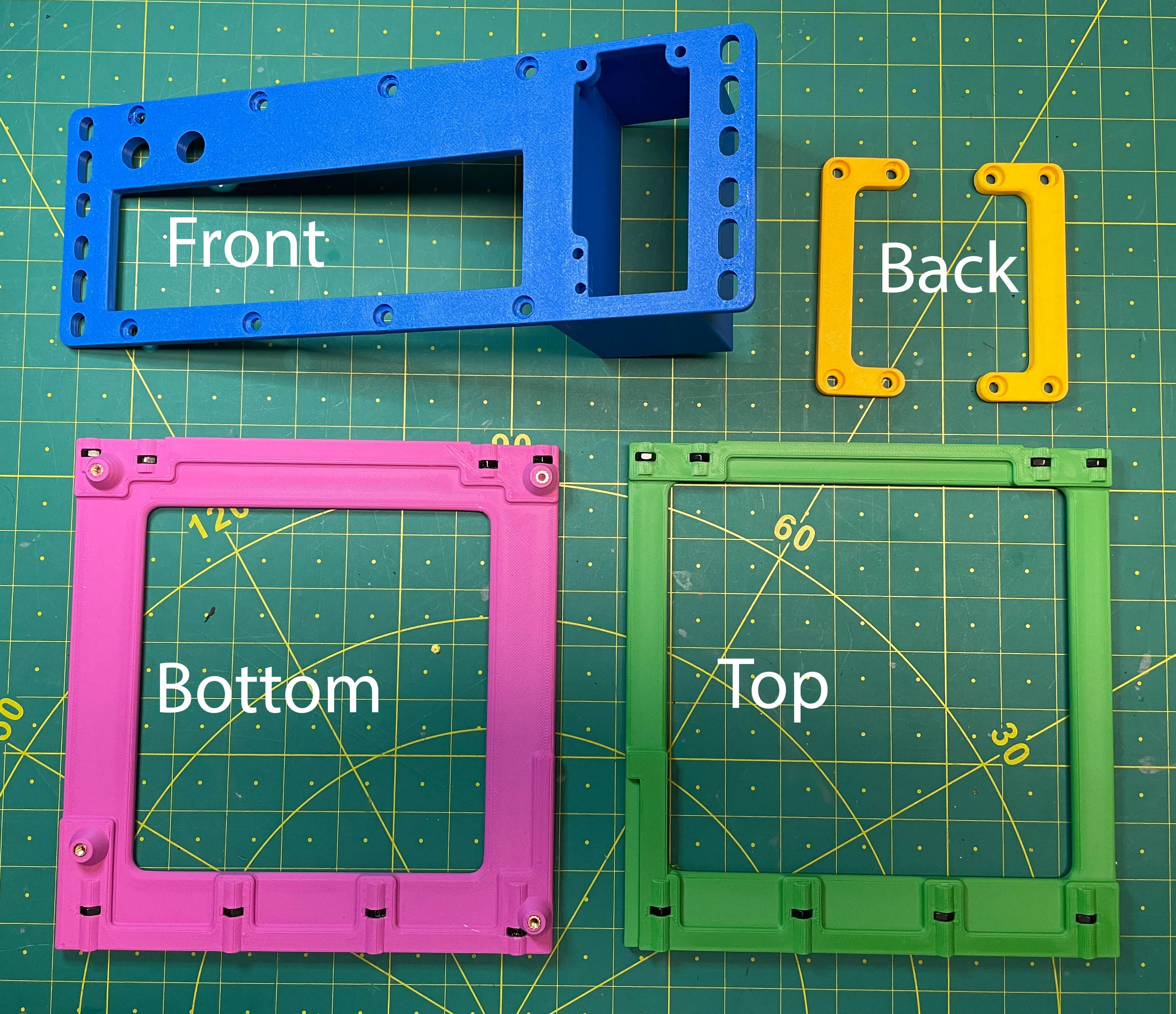
1.) print the parts
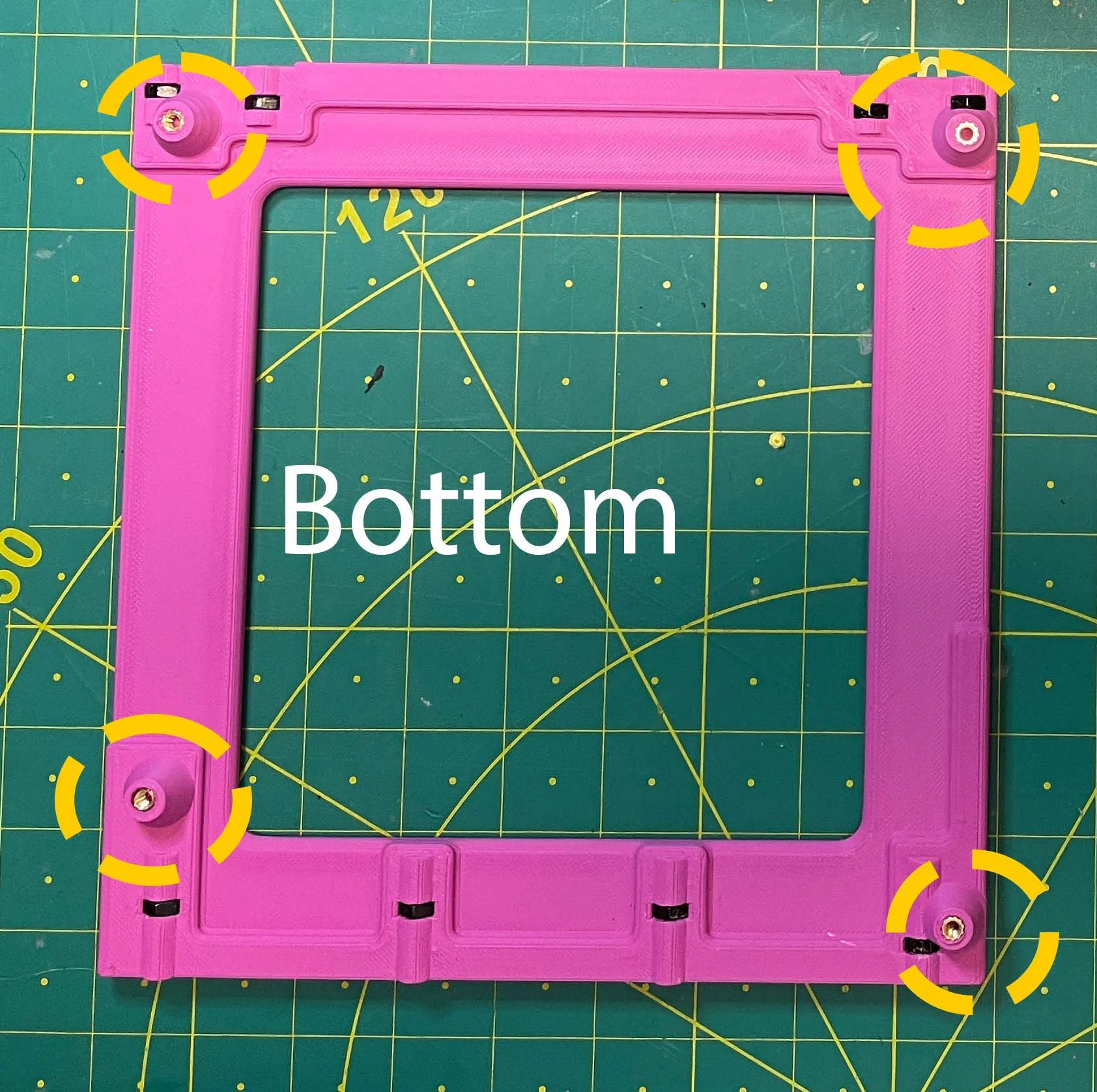
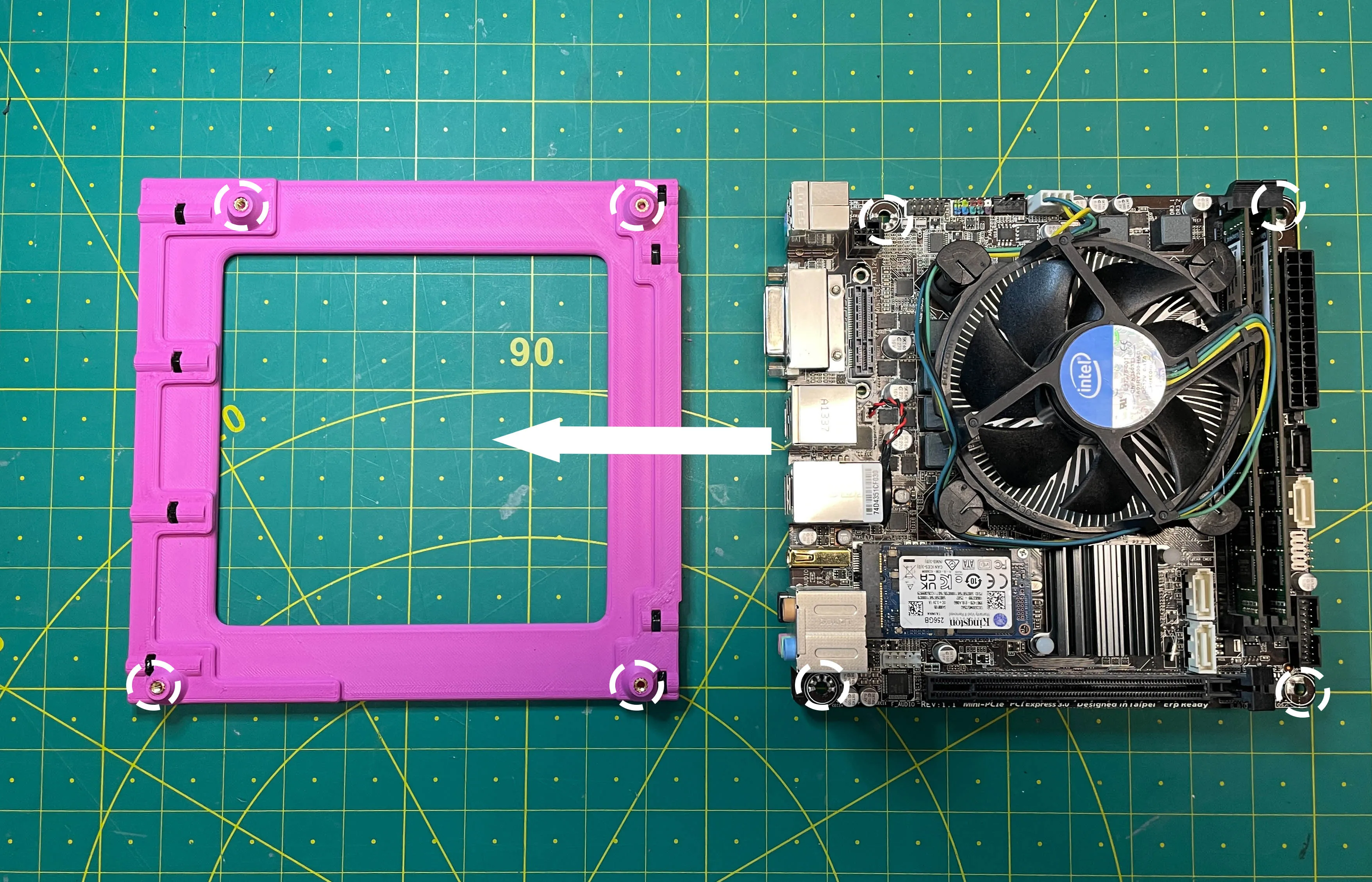
2.) press the 4 x M3 inserts into the bottom part
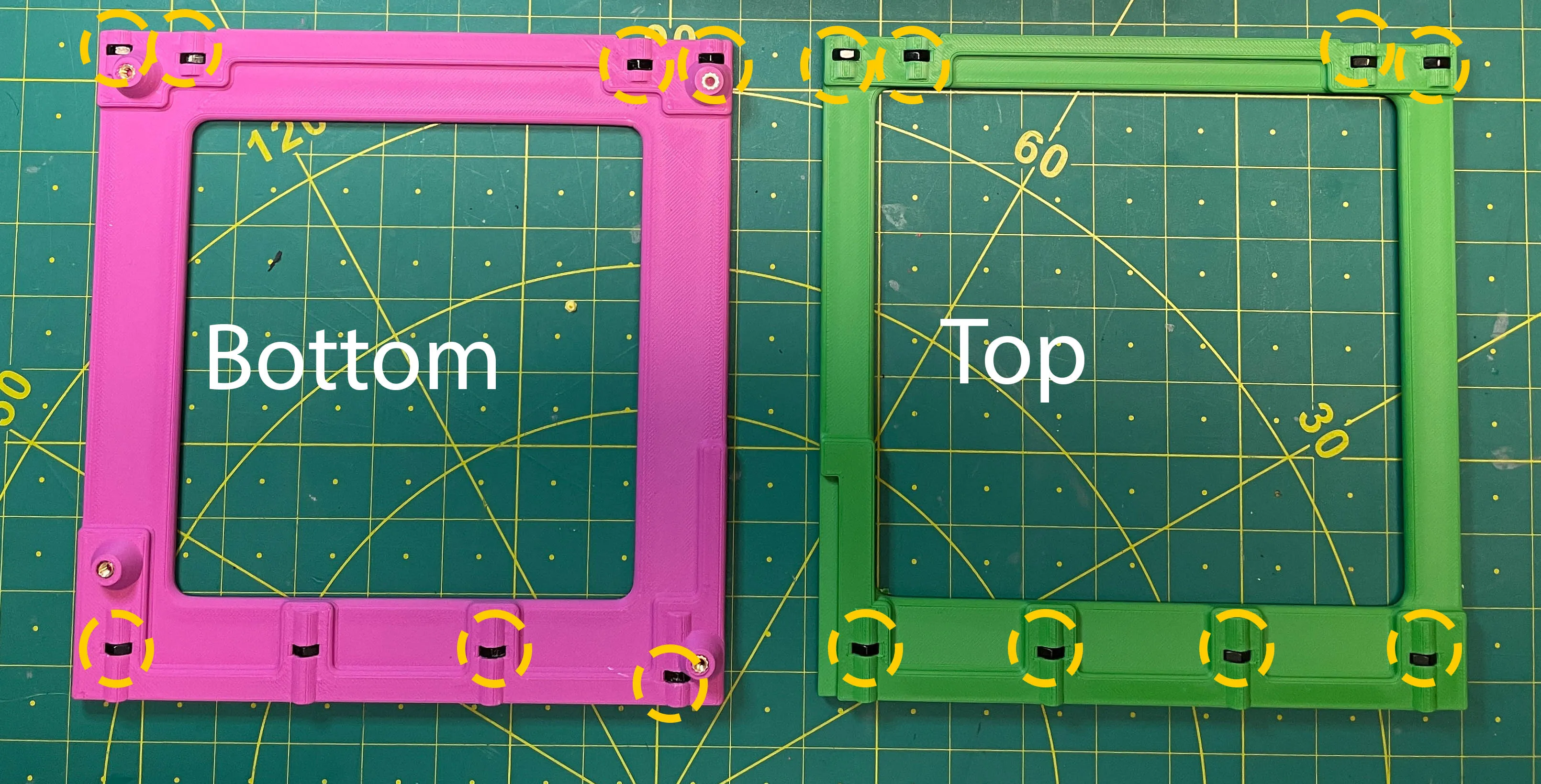
2.) put the 8 x M4 nuts into the bottom an top part
The nut must be inserted with the tip facing upwards, otherwise it will not work
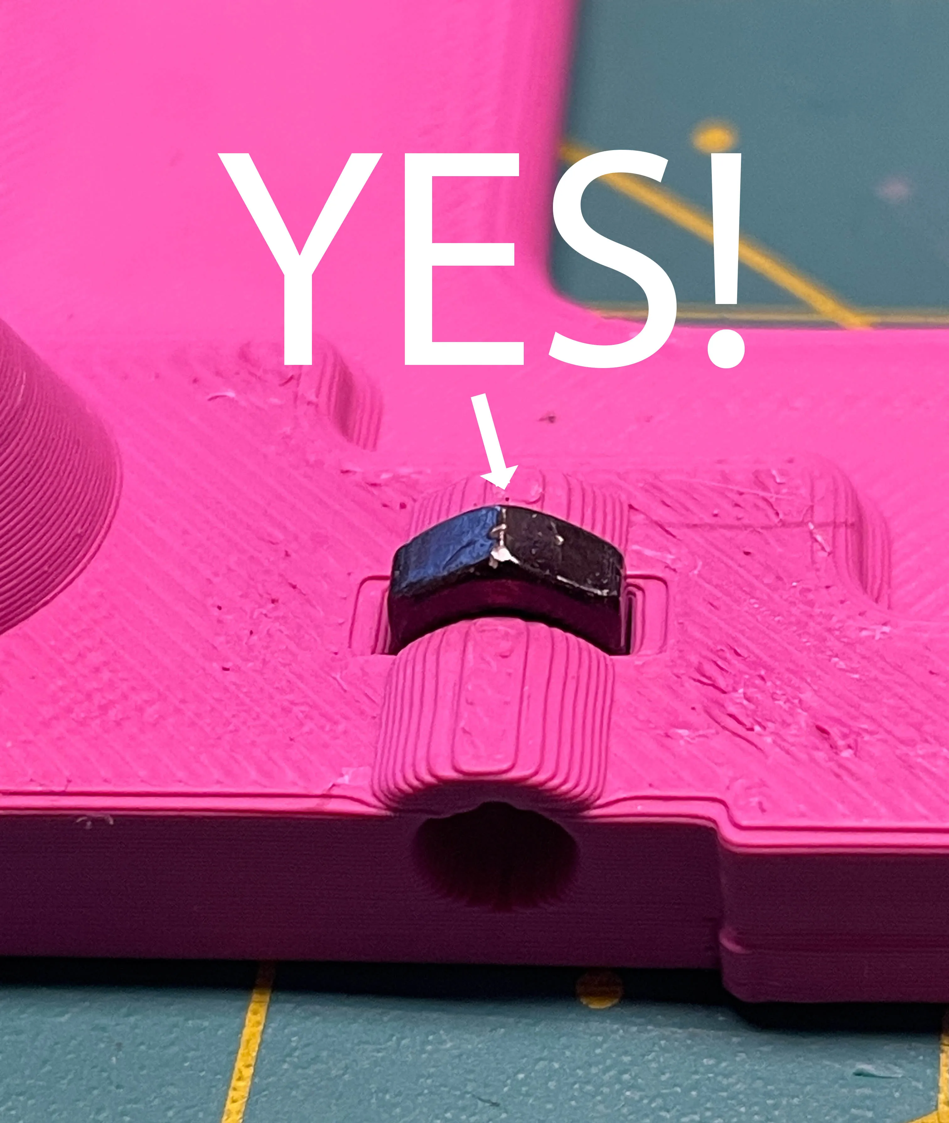
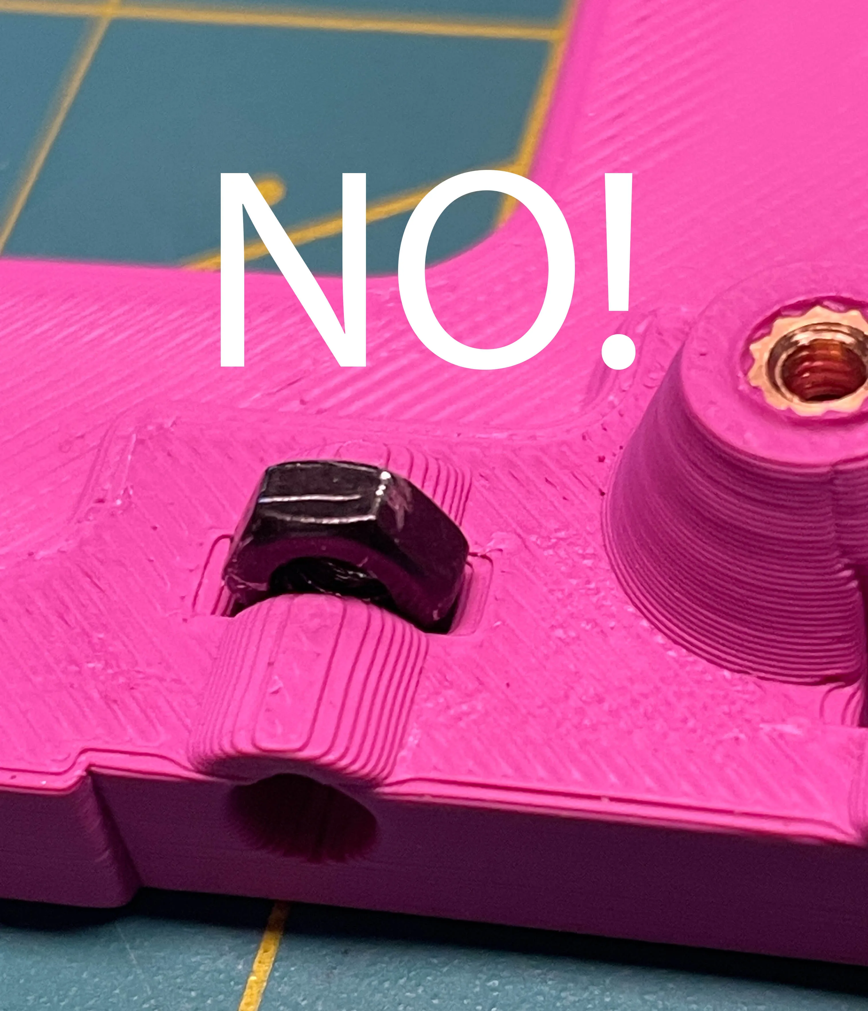
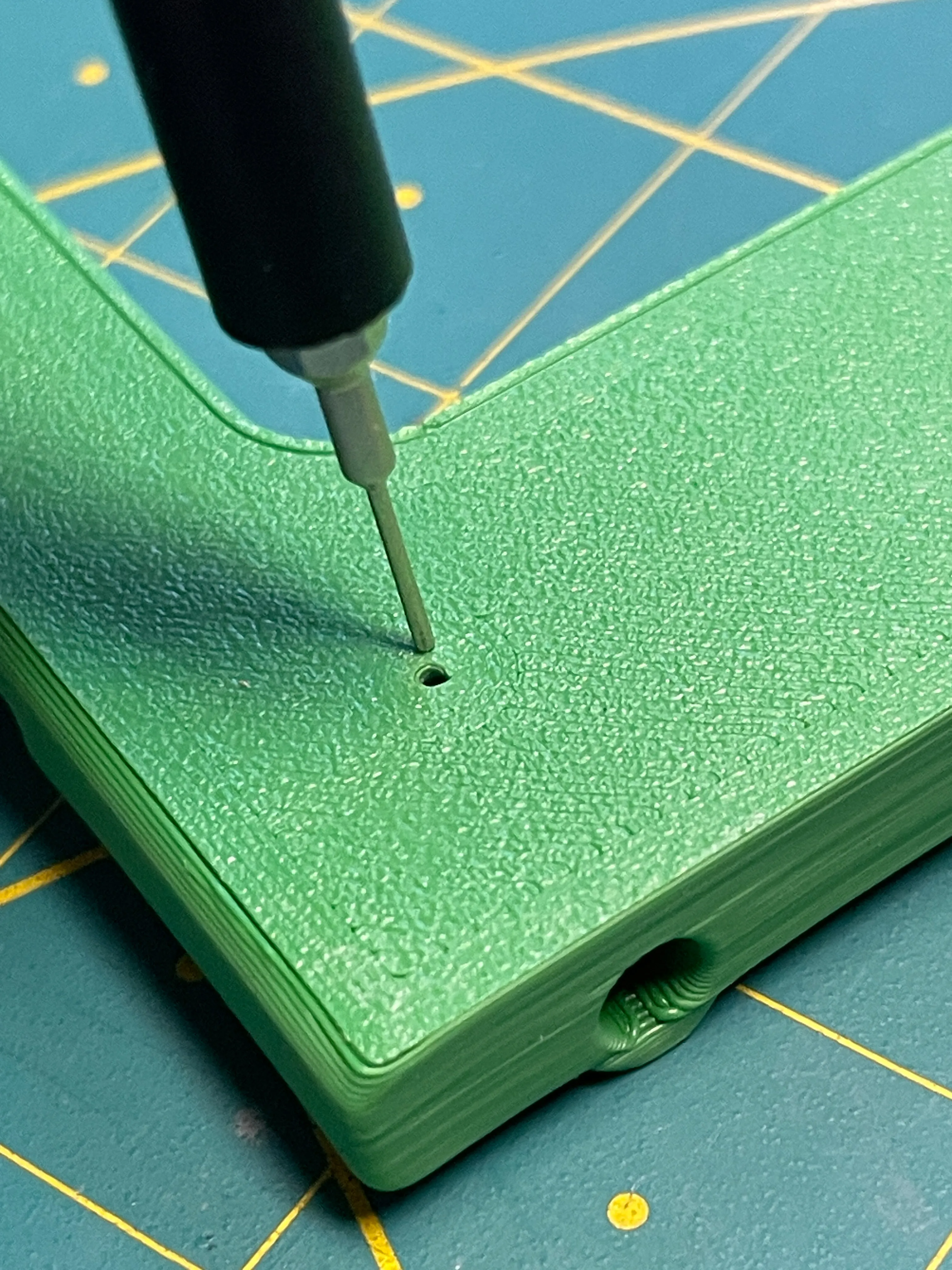
The nut can be pushed out again using a needle (SIM card removal) and the hole on the opposite side.
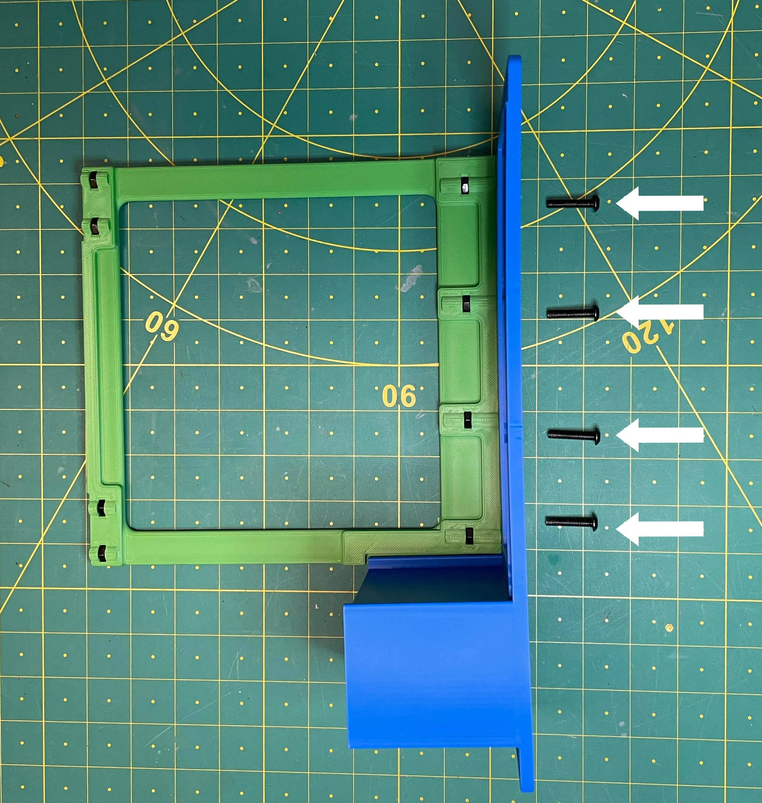
3.) Screw the front and top part together. Use four M4 x 20mm screws here.
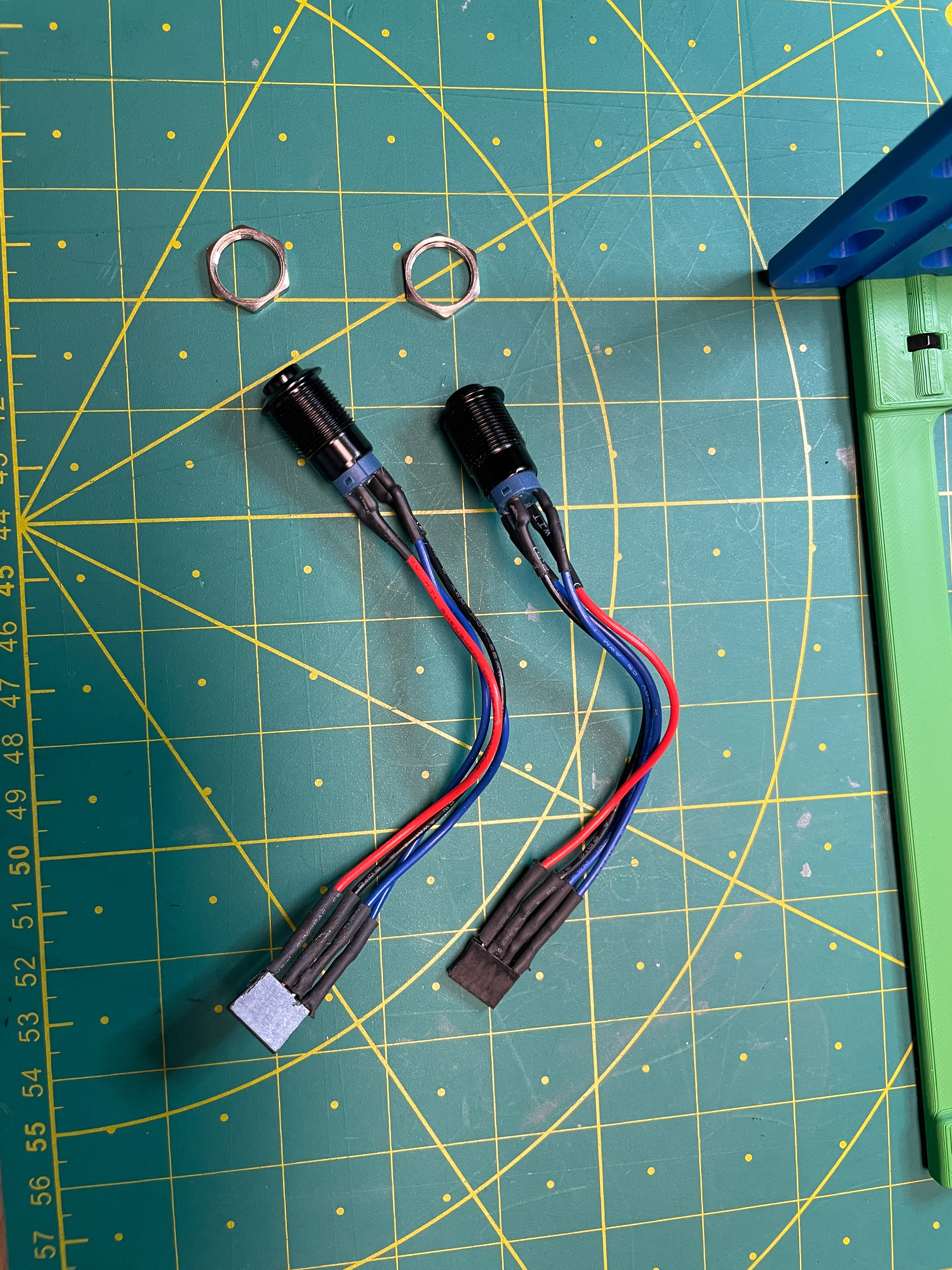
4.) Mount the LED buttons into the 12mm recesses.
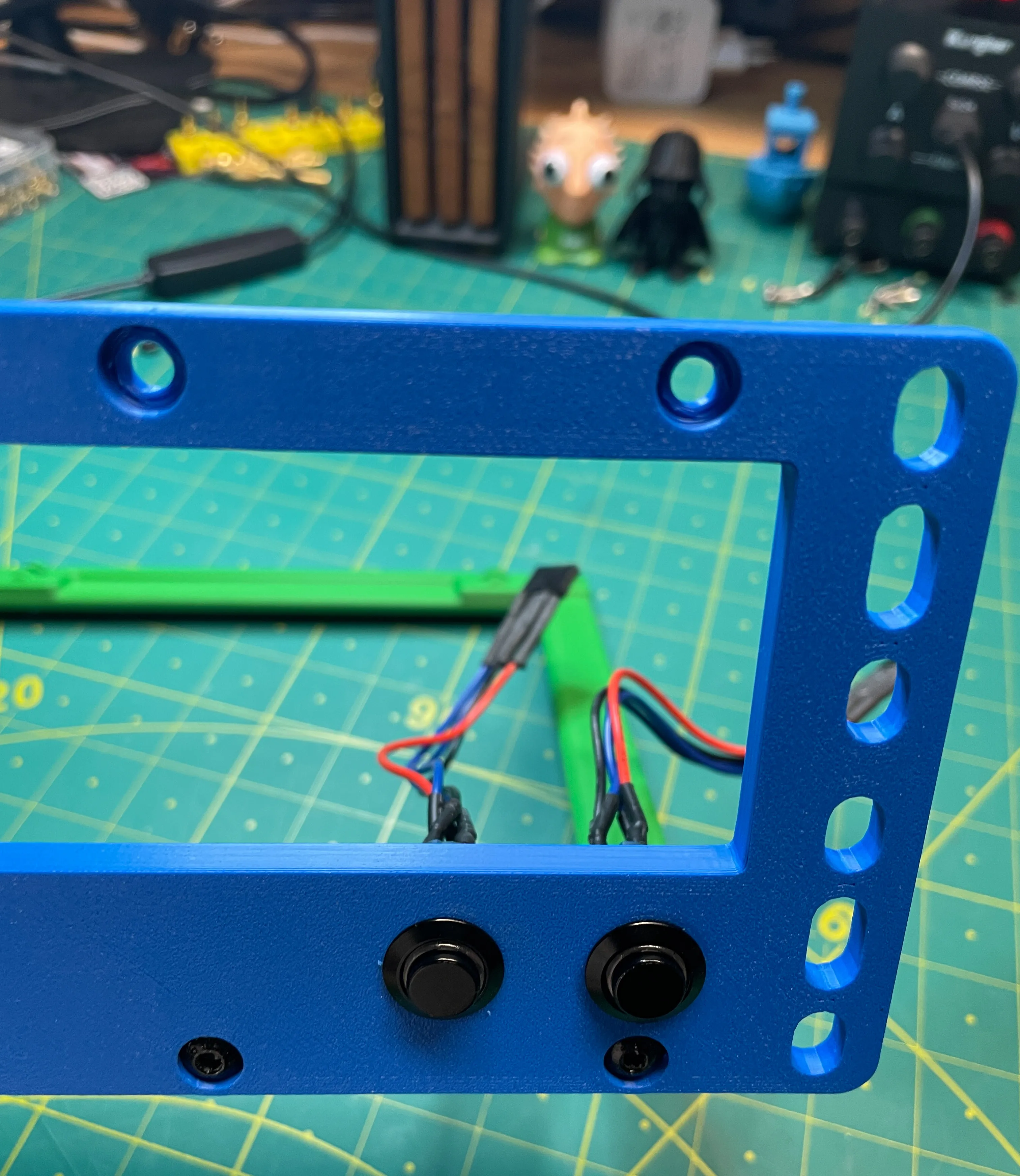
5.) Screw the two Back parts to the Top part. Use four M4 x 10mm screws here.
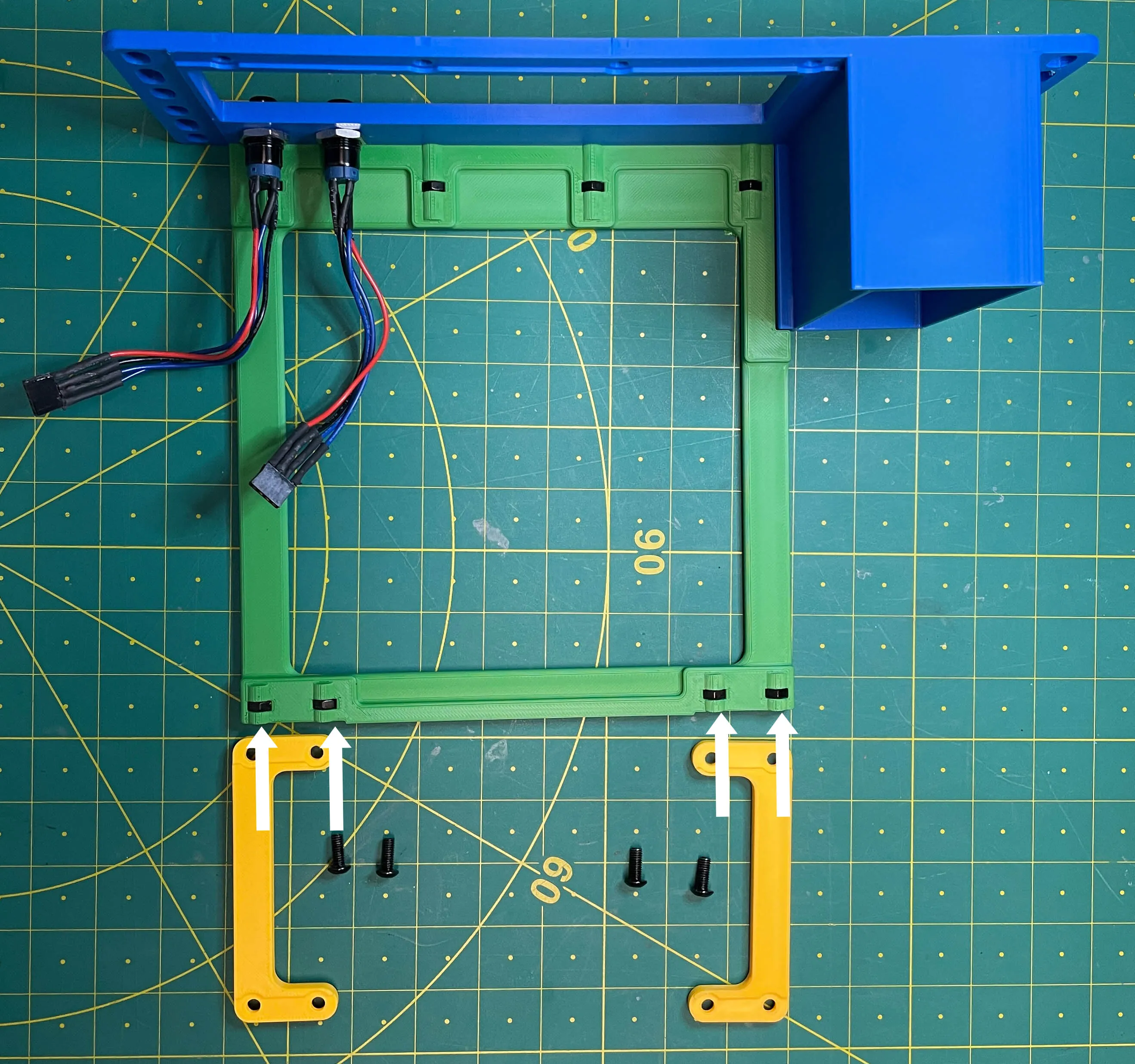
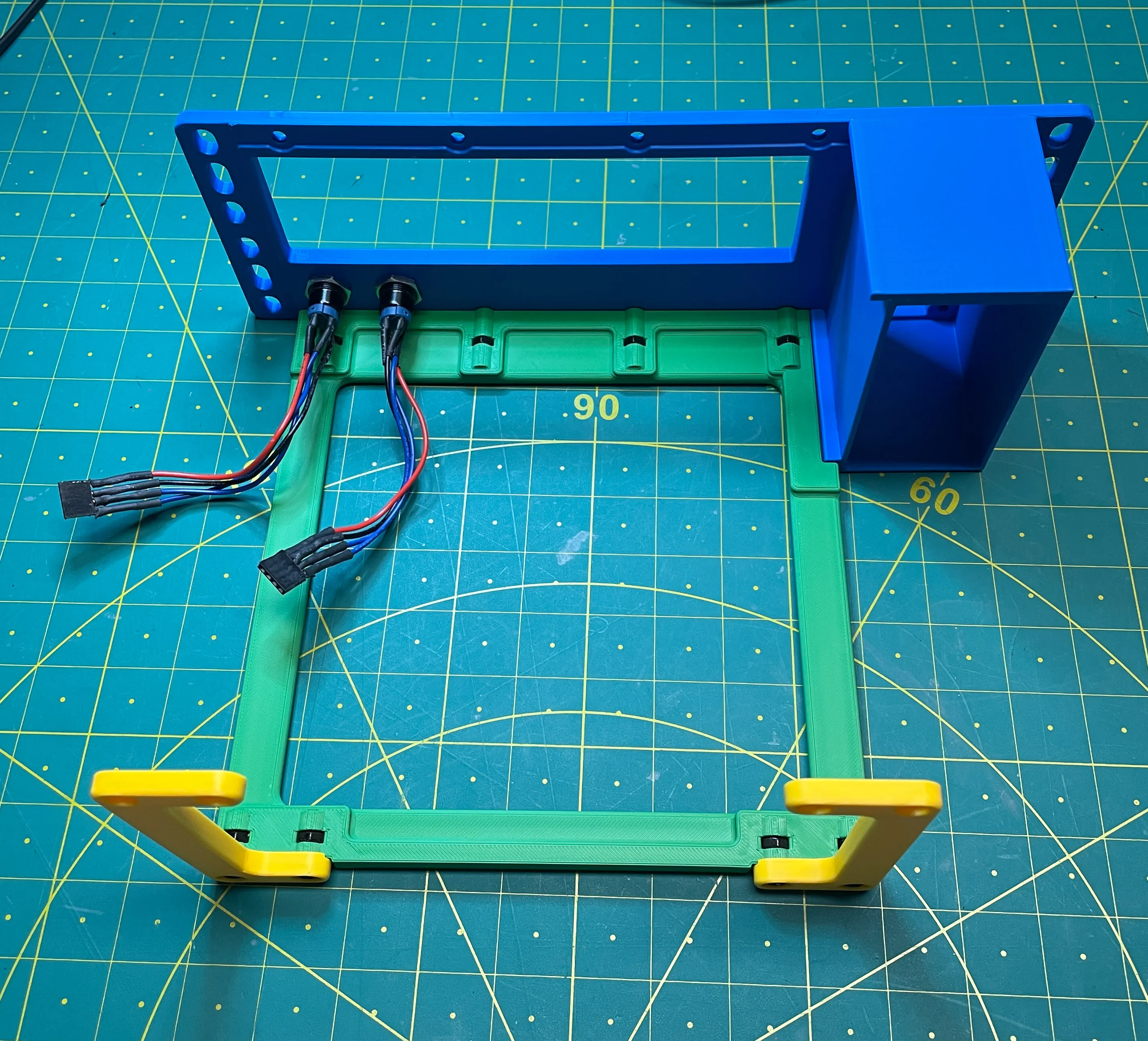
6.) Mount the Mini-ITX mainboard to the Bottom part
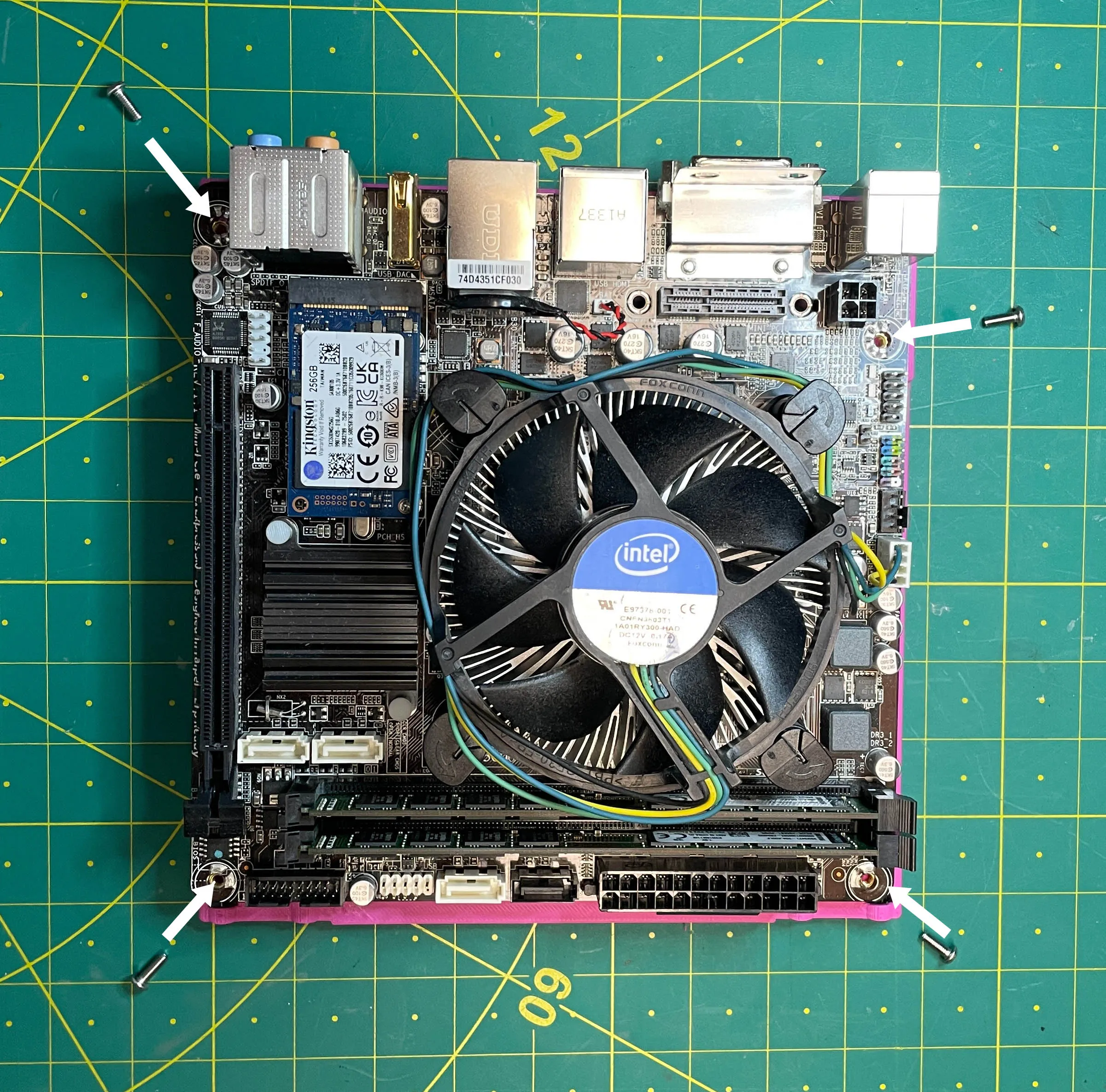
7.) Mount Bottom part to the rest of the parts. Use four M4 x 10mm and four M4 x 20mm screws here.
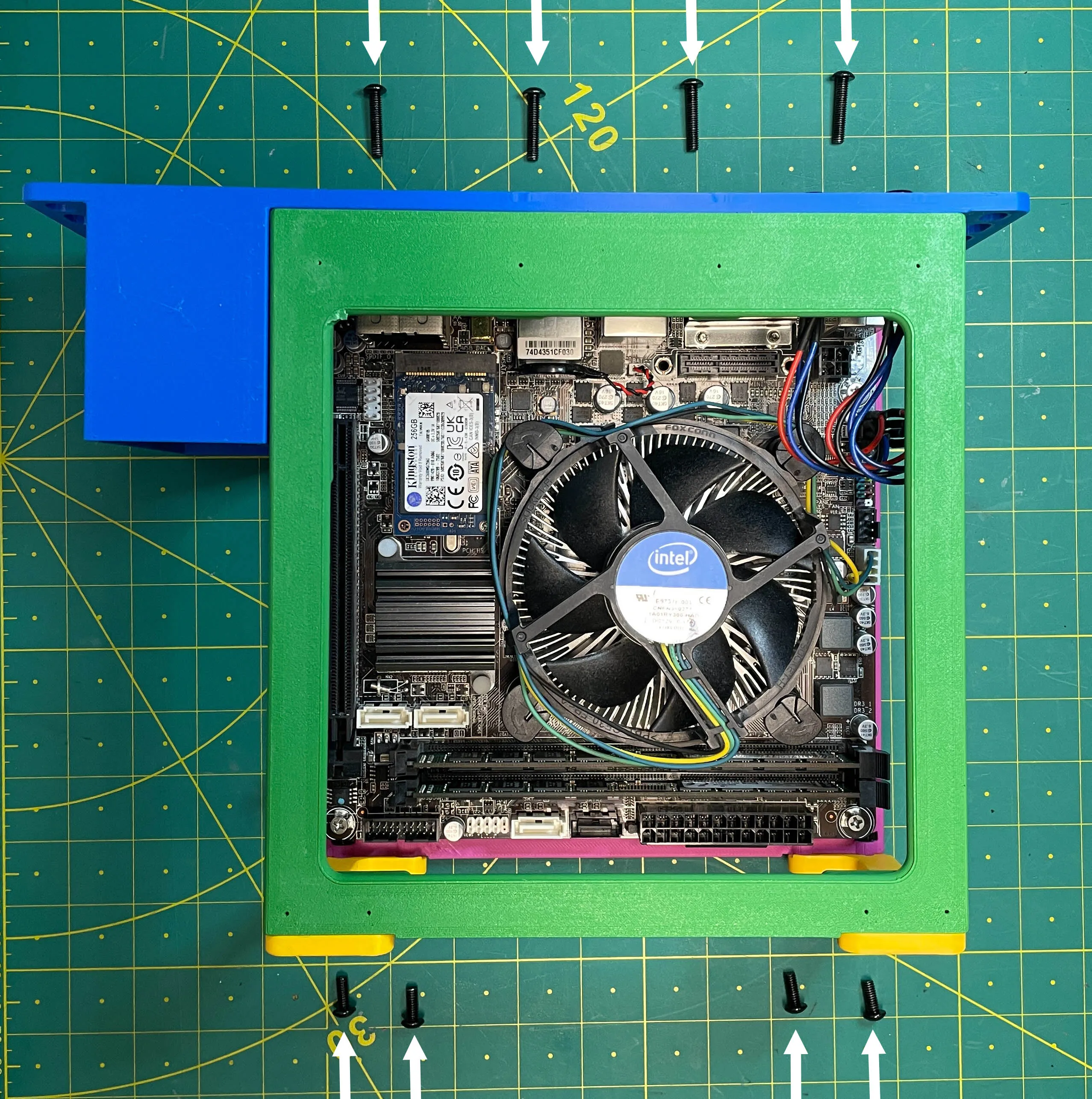

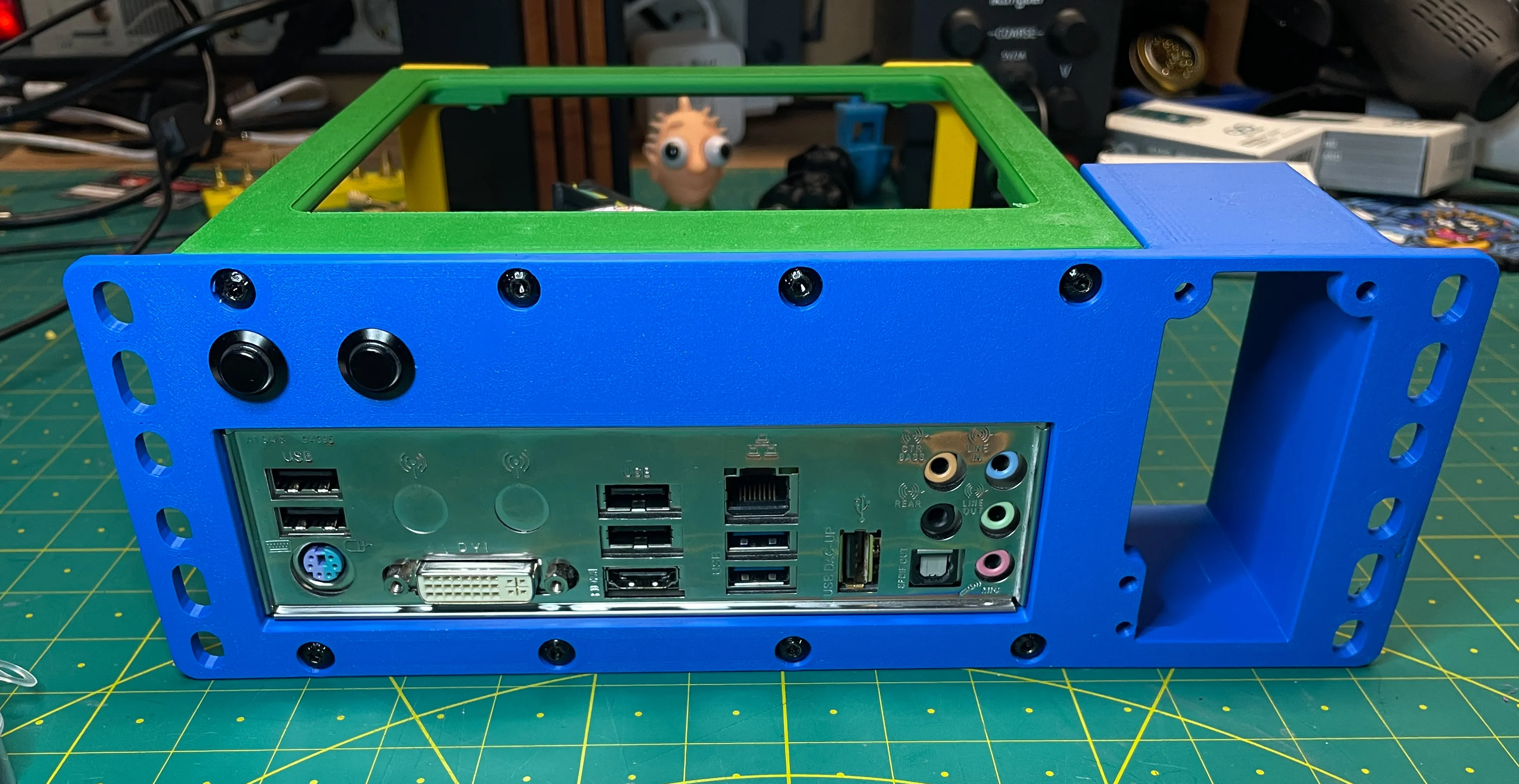
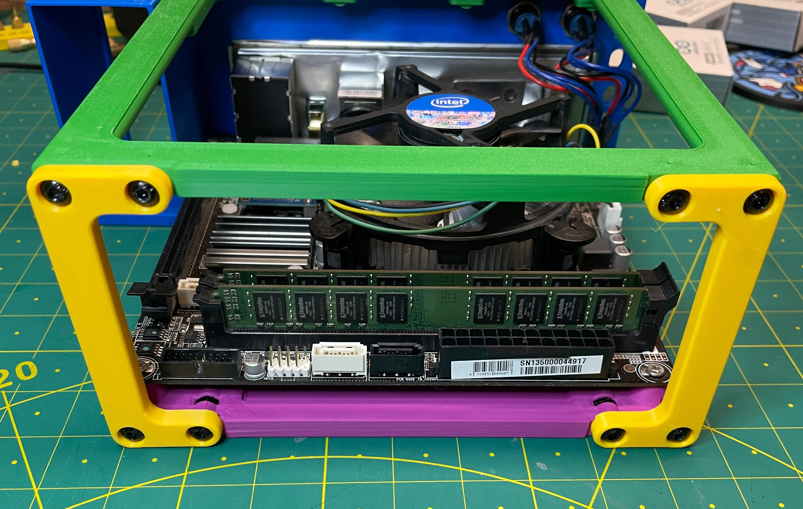
8.) Mount the Flex ATX PSU. Use four UNC 6-32 3/8 screws.
The Flex ATX bay is precision-adjusted to +0.5mm, and the power supply holds even without screws (PLA printing).
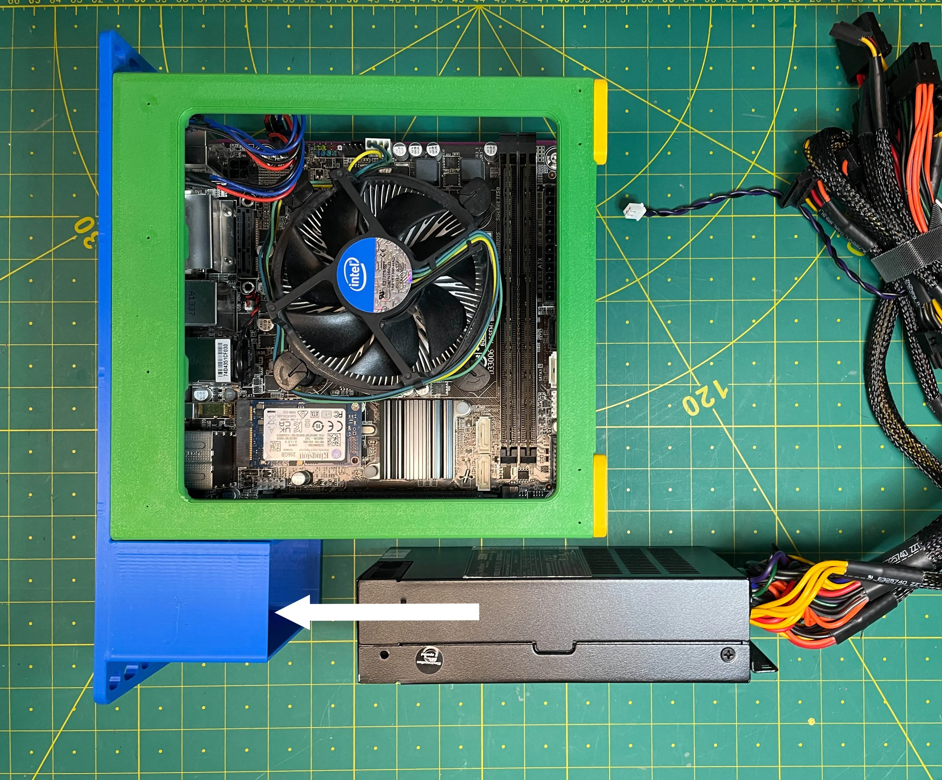
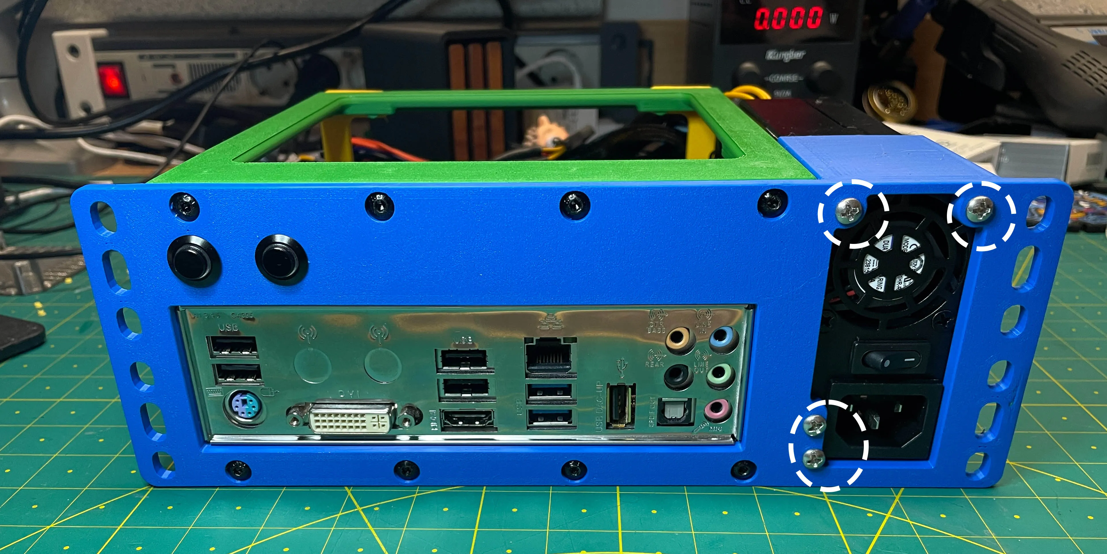
A Flex ATX power supply with removable cables would be ideal. But it is stable and works that way.
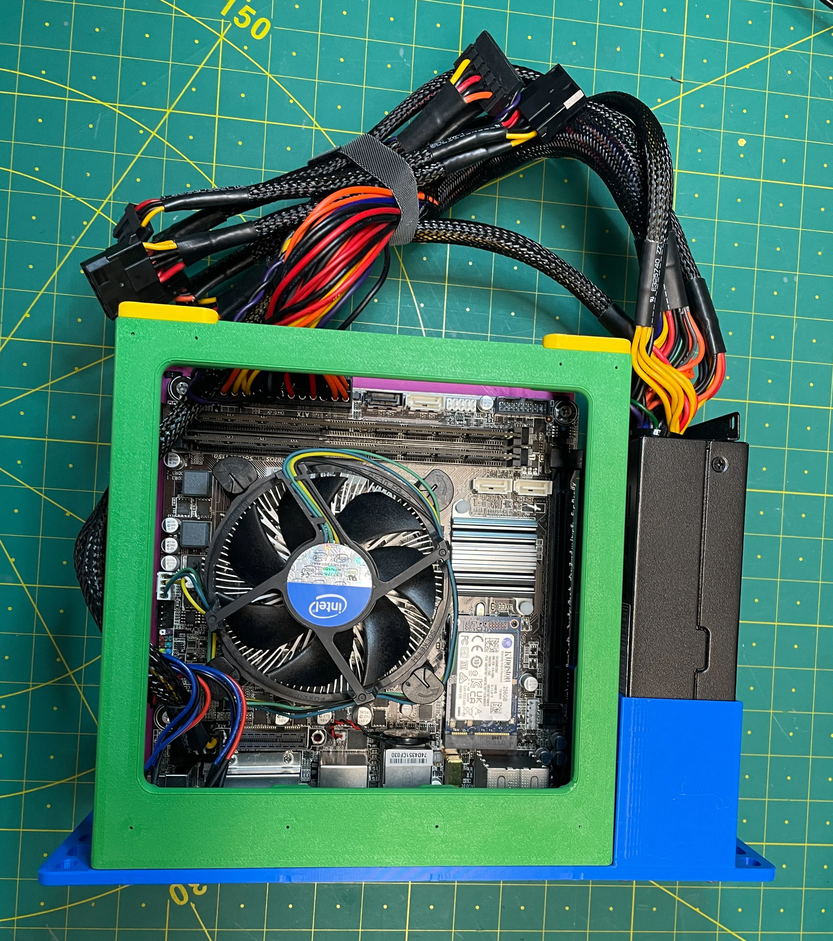
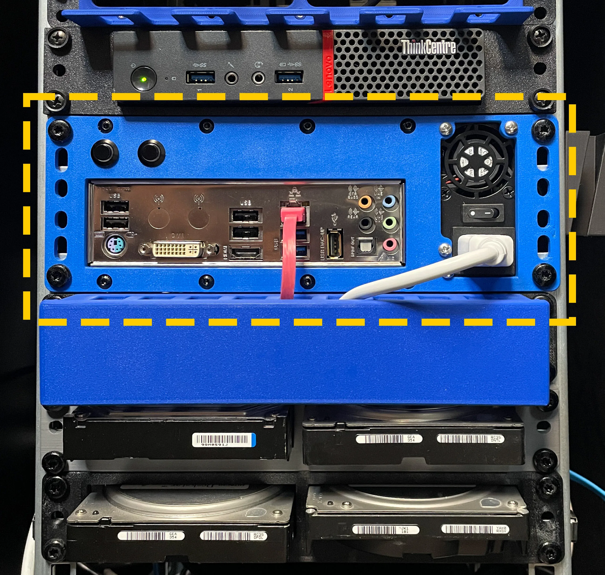
9.) Have fun with it!
License

You shall not share, sub-license, sell, rent, host, transfer, or distribute in any way the digital or 3D printed versions of this object, nor any other derivative work of this object in its digital or physical format (including - but not limited to - remixes of this object, and hosting on other digital platforms). The objects may not be used without permission in any way whatsoever in which you charge money, or collect fees.


Comment & Rating (55)