Search models, users, collections, and posts
Robotic Lawn Mower Additional Loops: Switch Box DIY
IP Report


GIF

GIF


Print Profile(4)

Box 1 Petg
Designer
3.2 h
2 plates

Box 2 Petg
Designer
4 h
2 plates

Box 1 PLA
Designer
2.1 h
2 plates

Box 2 PLA
Designer
2.7 h
2 plates
Open in Bambu Studio
Boost
13
28
2
4
3
1
Released
Description
Content has been automatically translated.
test
Switchable Additional Loops for Robotic Lawn Mowers – 3D-Printed Switch Boxes
Efficient Control of Additional Garden Areas
1. Project Overview
Brief Description:
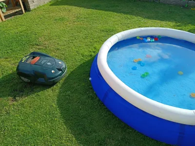
This project shows how a 3D-printed switch box can be used to flexibly extend or interrupt the boundary loop of a robotic lawn mower.
This allows secondary areas, pool bypasses, or temporary restricted areas (e.g., tent areas) to be easily included or excluded.
Boost Me (for free)
If you like my work, I would appreciate a boost. This shows me that I can continue working on the project to create even more designs. Thank you very much
Main Features:
- Compatible with above-ground, underground, or mixed-laid boundary wires
- Mechanical switches for easy operation
- Weather-protected housing design
- Expandable for multiple additional loops
2. Application Scenarios
- Secondary Areas → mow only when desired
- Pool Bypass → Robotic lawn mower passes by
- Temporary Restricted Areas → e.g. for garden parties or construction work
- Flexible Garden Design → without permanent relocation of the cable
3. Functional Principle (Assembly Instructions)
- Representation of the Main Loop (charging station → boundary wire → back)
- Additional loops are switched on or off via a switch
- Large Loops: End at a different point of the main loop
- Small Loops: End at the same point (note magnetic field compensation)

4. Technical Implementation
- Materials:
- Boundary Wire (Original or Compatible)
- 3-way Connector (waterproof)
- 3-way Toggle Switch (Round with 20 mm Diameter)
- 3D-Printed Switch Box
- Cable Connectors
Ground Anchors
MakerWorld: Lawn pegs for robotic lawnmowers
MakerWorld: Lawn nail for robotic lawnmowers
- Print Parameters (Suggestion):
- Material: PETG (weather resistant)
- Layer height: 0.2 mm
- Infill: 10 %
- Wall thickness: 3–4 perimeter
- Assembly Notes:
- Disconnect power to the charging station
- Disconnect cables at defined points and connect switch box
- Wire switches according to instructions
- Close housing
mower
mower accessories
mower accessory
mower setup
mower zone
mower zone control
robotic mower
robotic mower lawn saver
mower wiring
wiring
garden
garden accesoires
garden accesory
garden accessories
garden accessory
mower area
mower addon
mower modification
mower mod
robotic lawn mower
robotic lawnmover
robotic lawnmower
robotic lawnmower cleaner
robotic lawnmower wheels
lawn
lawn aeration
lawn aerator
lawn and garden
lawn mover
lawn mower
lawn mower attachment
lawn mower blade
lawn edge
WORX
worx aku mower
worx adapter
earth anchor
boundary
boundary wire
boundary wire peg
grass anchor
grass
ground anchor
husquarna
lawn pegs
robotic lawnmower loop
mower loop
Documentation (2)
Assembly Guide (2)
Montageanleitung - Deutsch.pdf
assembly instructions - englisch.pdf
License
This user content is licensed under a
Creative Commons Attribution-Noncommercial-Share Alike
Comment & Rating (2)