
10" Rack Power Distribution Unit
Print Profile(1)

Description
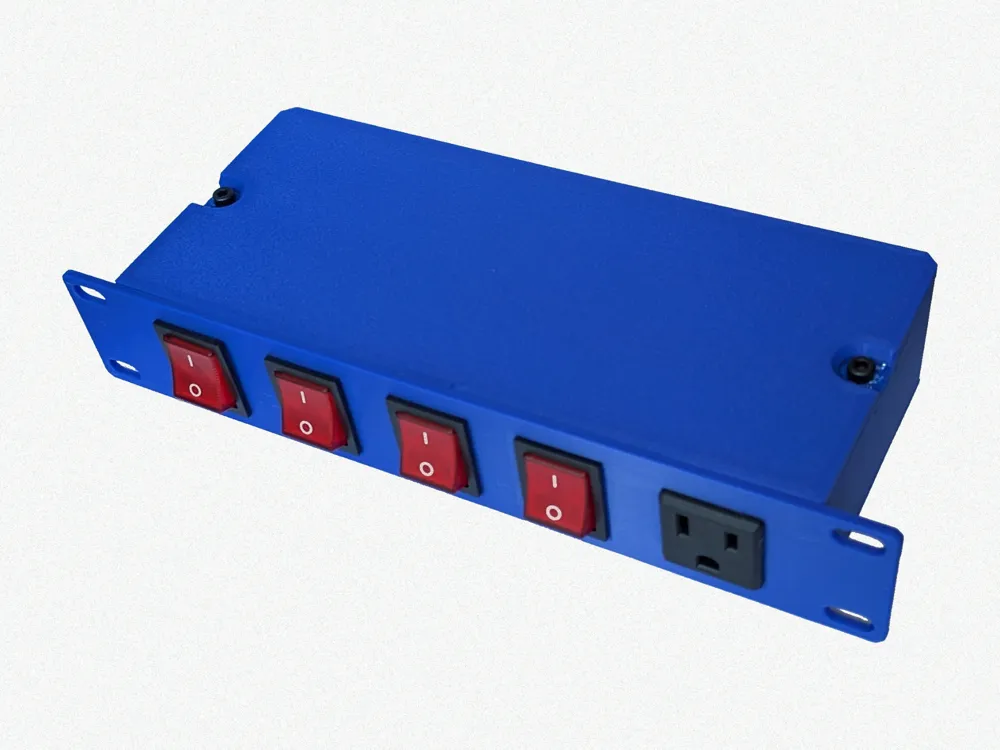
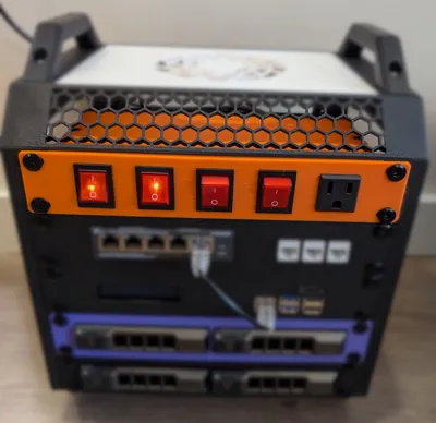
Simplified power management for 10" Racks
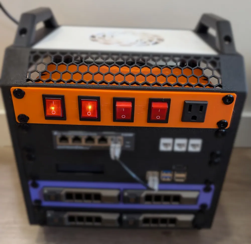
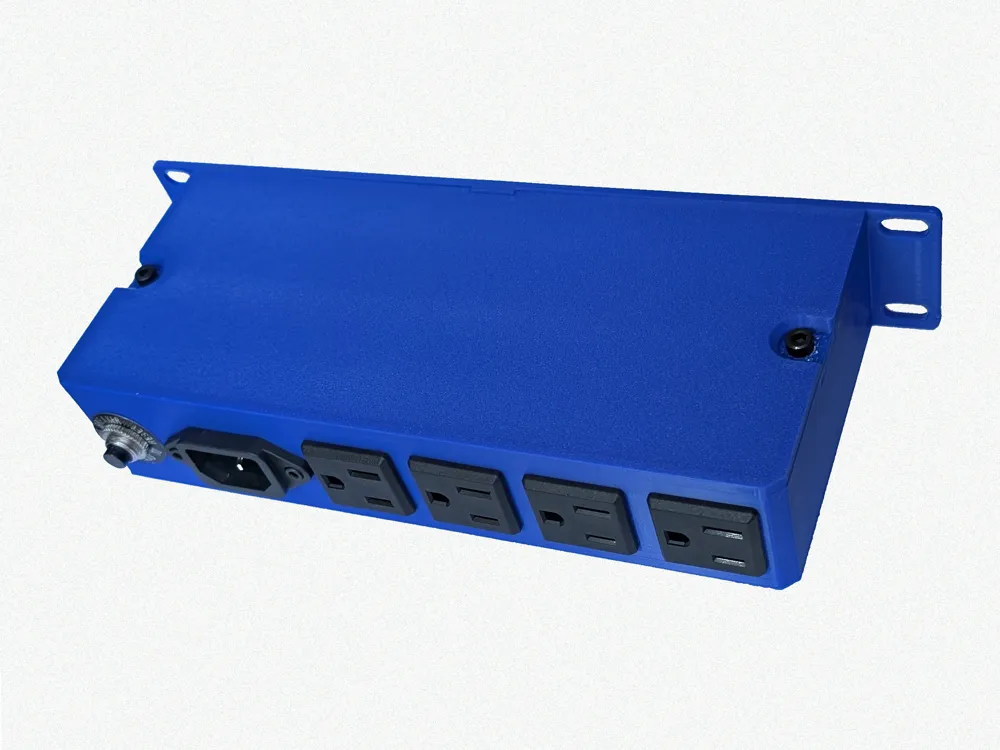
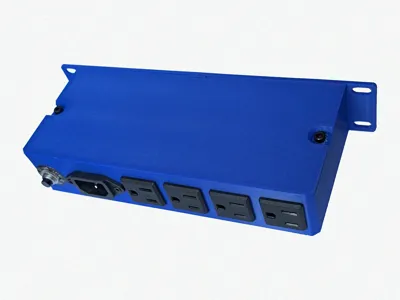
A PDU for 10" Racks, such as the Lab Rax, Rack Mate, or any other rack in the 10" format. Plug stuff in the back, switch them on or off in the front!
This design takes inspiration from https://www.printables.com/model/1247459-10-inch-rackmount-pdu
Features
- 1 Externally facing Power Outlet
- 4 Internally facing power outlets managed by 4 externally facing switches
- Includes a breaker to prevent over-current situations
BOM
| Count | Description | Purchase Link |
|---|---|---|
| 1 | 10A Button Breaker | Amazon |
| 4 | Panel Mounted Lighted Rocker Toggle Switch | Amazon |
| 5 | Panel Mounted NEMA Power Socket | Amazon |
| 1 | Panel Mount C14 AC Socket | Amazon |
| 1 | 14 AWG C14 AC Power Cable | Amazon |
| 36 | 16-14 AWG Female Spade Connector | Amazon |
| 12 | 16-14 AWG Piggyback Spade Connector | Amazon |
| Various Lengths of 14 AWG Stranded Wire | Amazon | |
| 2 | M4 Threaded Heat-Inserts | Maker Supply |
| 2 | M4x8mm Screws | Maker Supply |
| 2 | M3x6mm Screws | Maker Supply |
| 2 | M3 Nuts | Maker Supply |
Tools
Soldering Iron - Maker Supply
Soldering Iron Heat Set M4 Tip - Maker Supply
Wire stripper and crimper - Amazon
Hex wrenches for the M4 and M3 screws - Amazon
Assembly
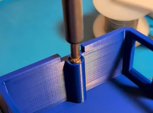
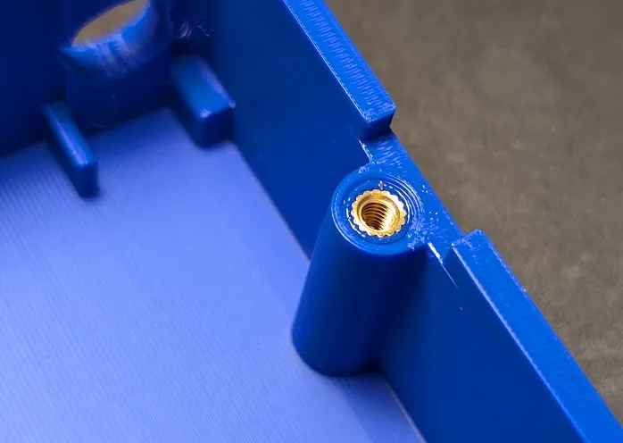
Insert the two heat set inserts in the body and set them in place with the soldering iron. Do your best to keep them vertical.
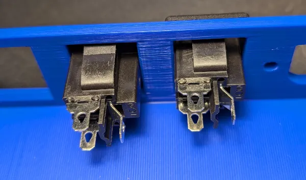
Snap all of the panel mount power sockets in place. They should only fit when oriented correctly.
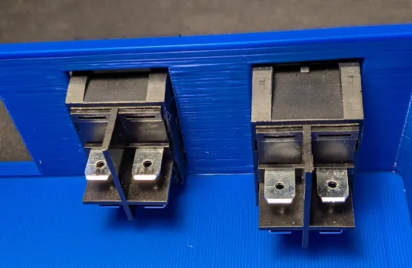
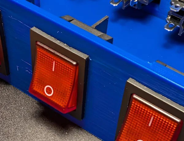
The switches snap into place - make sure they are oriented so the on-line is pointing upwards.
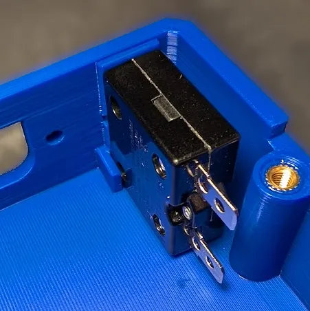
Push the breaker into place with the leads opposite the side wall of the body and screw the nut into place to secure it. It may take a little force to get it in place as the harness for it is snug.
Attach the C14 Socket and secure in place with the M3 screws and nuts.
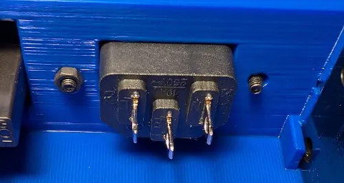
Cut and crimp the wires as needed. You'll be using the piggyback spade connectors to chain the ground (green) to the sockets and neutral / hot to the switches.
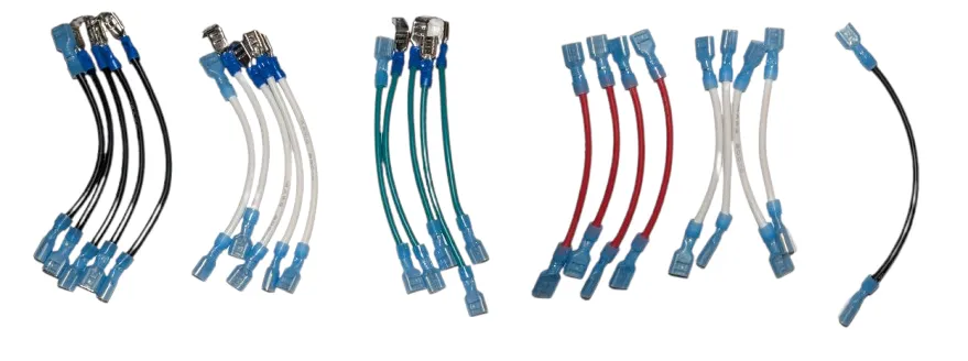
The colors you choose are really up to you but I chose:
- Green for ground
- White for neutral
- Black for live before the switch
- Red for live after the switch
Plug in all of the wires based on the following diagram:
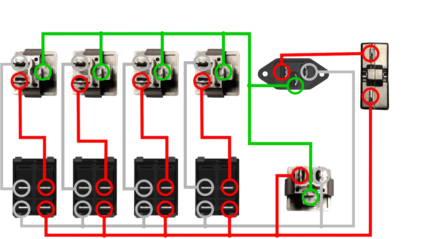
Note that the diagram shows all parts from the rear.
Once everything is wired you can put the lid on and secure it with the M4 screws.
You're ready to test the PDU.
Troubleshooting
The lights for the switches are always on.
You've wired the switches backwards. The wires from the C14 socket / breaker should be attached to the bottom. The wires to the NEMA socket should be on the top of the switch.
The lights turn on but power doesn't flow to the NEMA socket.
You may want to re-wire that specific socket - the spade connectors sometimes get a poor connection when not properly crimped.
License



Comment & Rating (17)