Switchbot Blind Tilt Plantation Shutter Adapter


Print Profile(1)
Description
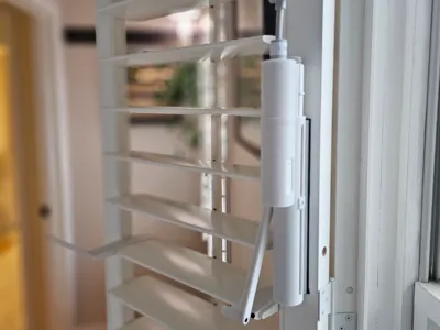
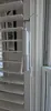
SwitchBot Blind Tilt Adapter for Use with Plantation Shutters
I created this to convert a SwitchBot Blind Tilt to work with my plantation slat type shutters.
~ This Requires Modifications! ~ It is not Universal! ~
At a minimum - the Slat Clip and Slat Bridge will need to be modified, or replaced with components, so that they will fit to your size and profile of slat. This is simply meant to offer a starting point for others that may want to automate their shutters in a similar way. I have included .step models of the Slat Clip, Slat bridge, and Linkage.
I hope you find it a useful starting point for automating your own shutters.
Materials Used -
- 1 - M3 X 16 course thread button head screw
- 2 – M3 X 25 course thread button head screws
- Double sided tape of your choosing.
- 1 - length of 1.5mm Stainless steel wire. Length based on your needs.
Printing Suggestions -
- Determine how you will mount the adapter and mirror/rotate parts as needed.
- I printed in PETG. If you live in a warmer climate or will be installing in window(s) receiving direct sunlight, consider higher temp and UV tolerant materials.
- Use supports and Brims.
- Print all objects with 100% infill.
Adapter Assembly -
- Connect the drive screw and drive gear using the key pin.
- Insert drive gear assembly into Bind Tilt.
- Lubricate moving parts.
- Insert Blint Tilt into the adapter case and thread drive screw into carriage to fully seat.
- Snap Motor Cap into the Adapter Body.
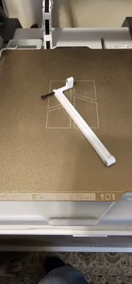
- Screw Linkage into carriage using 1 - M3 X 16 course thread button head screw.
- Screw 1 M3 X 25 course thread button head screw into the Linkage arm at the elbow as reinforcement.
- Insert linkage into the slat bracket and secure using 1 M3 X 25 course thread button head screw.
Slat Bridge -
- Insert the stainless wire into the hole in Slat Bridge_A. I chucked the wire into a cordless hand drill like it was a bit and inserted the wire using continuous low speed. There needs to be enough exposed wire to engage fully into the slot of Slat Bridge_B.
Installation – Mount the assembly and calibrate following the manufacturer’s instructions.
Suggestion - There is a small dot on the case that indicates the center of travel. Mount the case with the slats horizontal and the travel in the center of its range of movement to ensure full movement in both directions.
License
You shall not share, sub-license, sell, rent, host, transfer, or distribute in any way the digital or 3D printed versions of this object, nor any other derivative work of this object in its digital or physical format (including - but not limited to - remixes of this object, and hosting on other digital platforms). The objects may not be used without permission in any way whatsoever in which you charge money, or collect fees.
Comment & Rating (0)