
bmcu-A1/A1 mini rotating stand_v2 (low height), horizontal placement stand model added on 2026.4.23
Print Profile(8)


Description

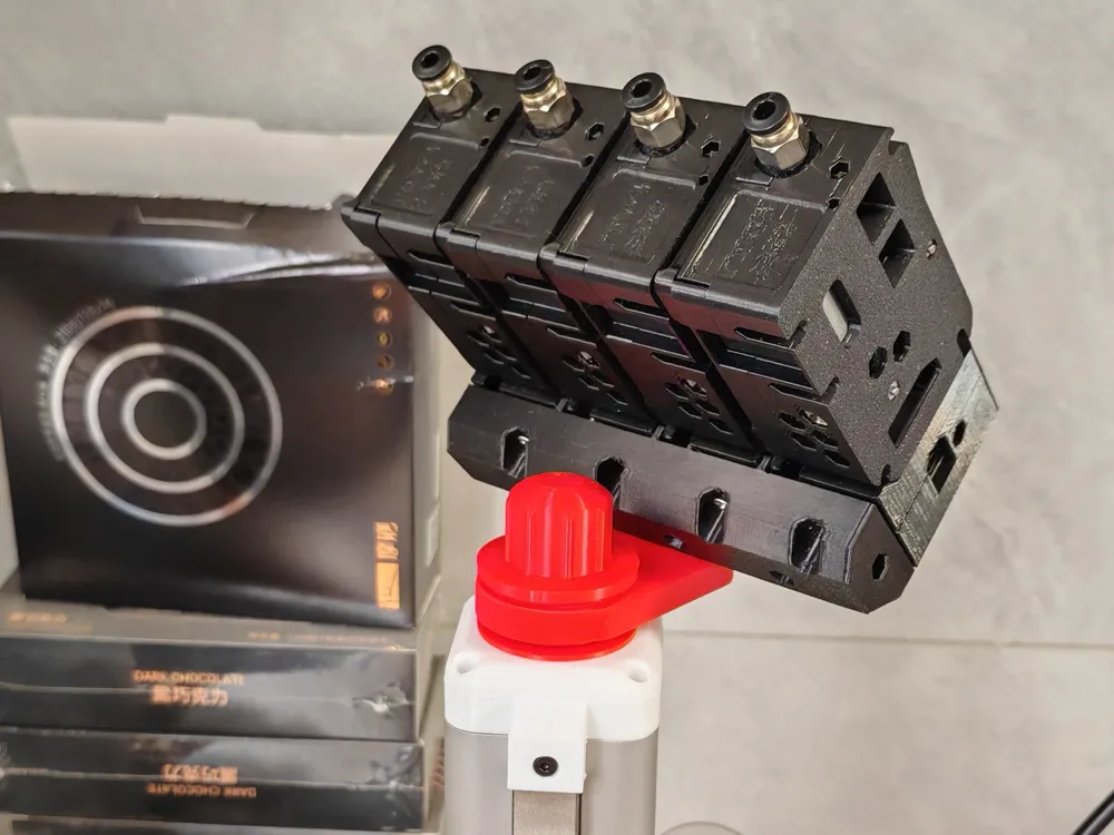
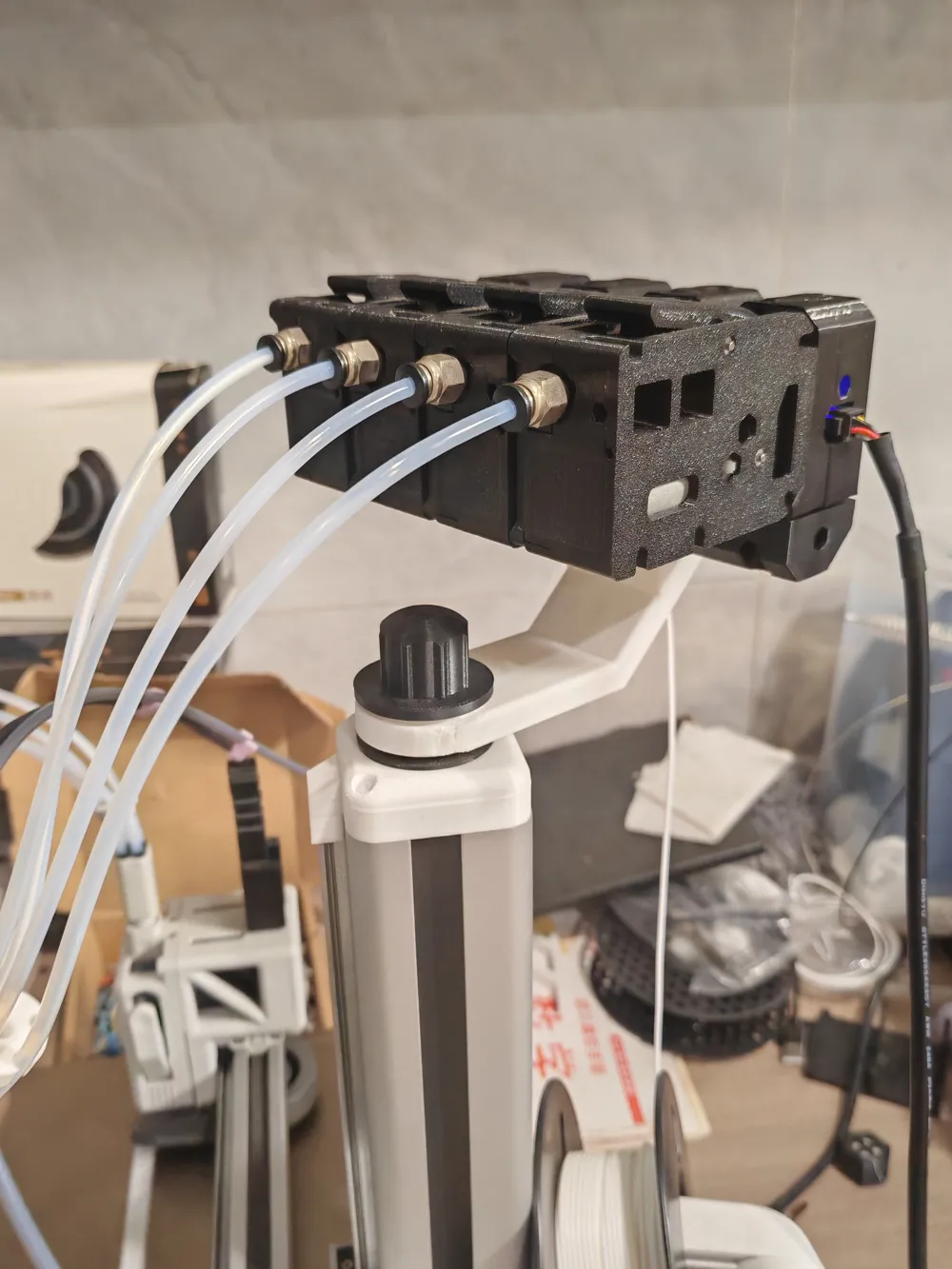
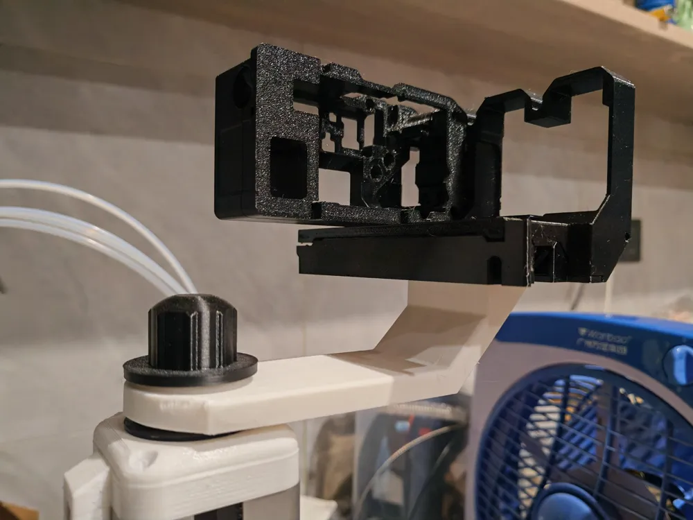
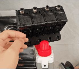
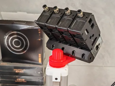
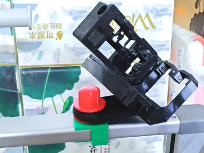
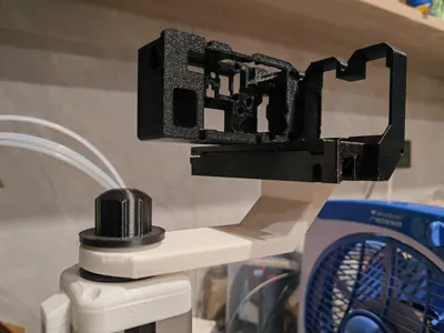
Added on 2026.4.23: A horizontal placement stand model has been added. After replacement, the bmcu will be horizontal on the stand. The only change from the original is the stand's connector, with no other modifications. Therefore, if you have printed the v2 model and want to replace it with the horizontal placement version, you only need to print plate 2 in the new horizontal profile and replace it with the new connector.
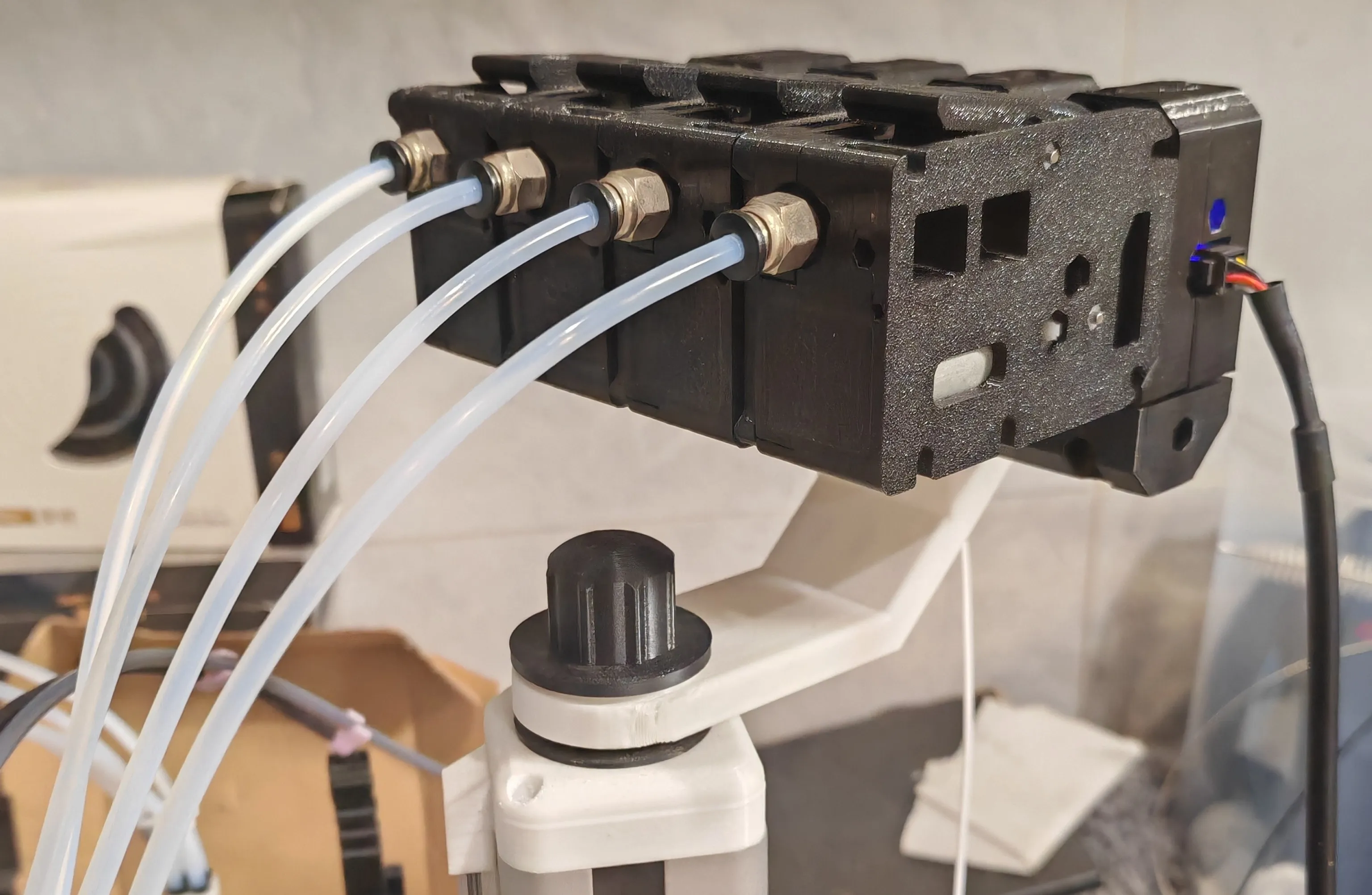
bmcu-rotating stand_v2 (low height):
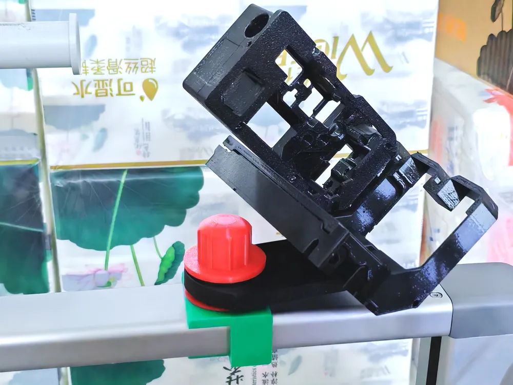

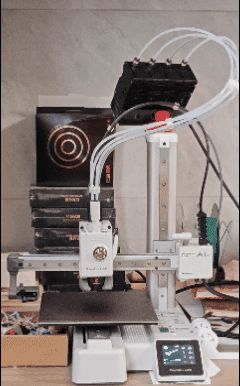
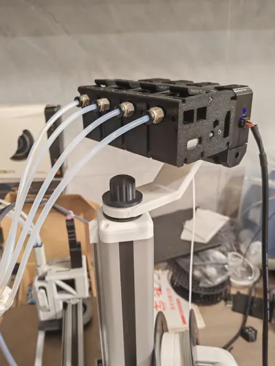
The second version of the bmcu rotating stand is here. The second version is lower in height than the first, uses less material, and has a shorter printing time. It is also compatible with the base of the first version of the rotating stand and can be directly replaced. At the same time, the A1 base has also been optimized to be more stable when clipped onto the beam.
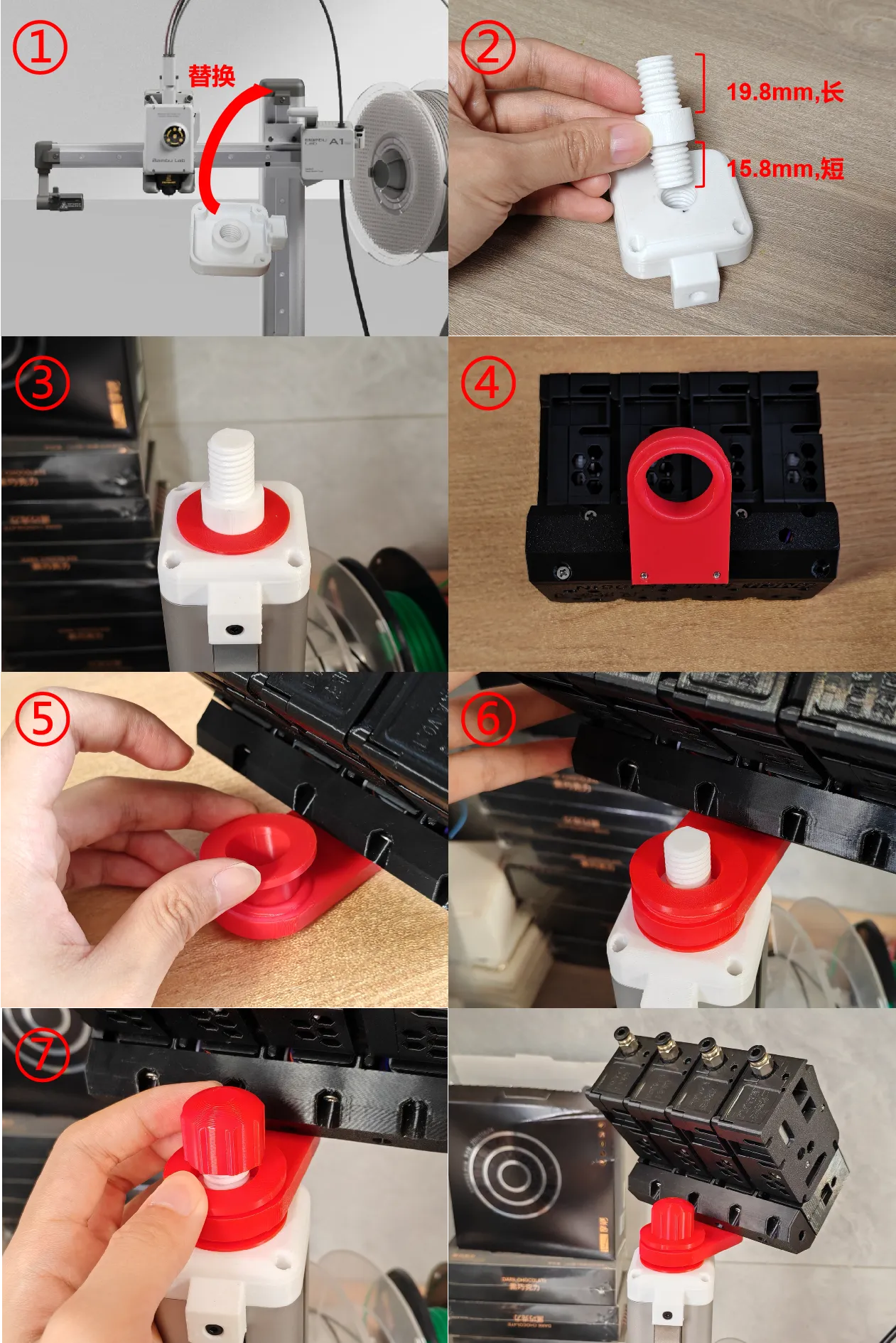
Specific assembly tutorial is as follows: A1 mini (Those replacing from the first version to the second can skip steps 1 and 2):
1.Replace the original A1 mini cable cover with the printed cable cover
2.Screw the shorter end of the screw into the replaced cable cover
3.Place the washer onto the bottom of the base screw
4.Replace the original bmcu stand with the stand connector
5.Place the bushing into the stand connector
6.Slide the installed bmcu stand connector onto the base screw
7.Screw the nut onto the base screw (complete)
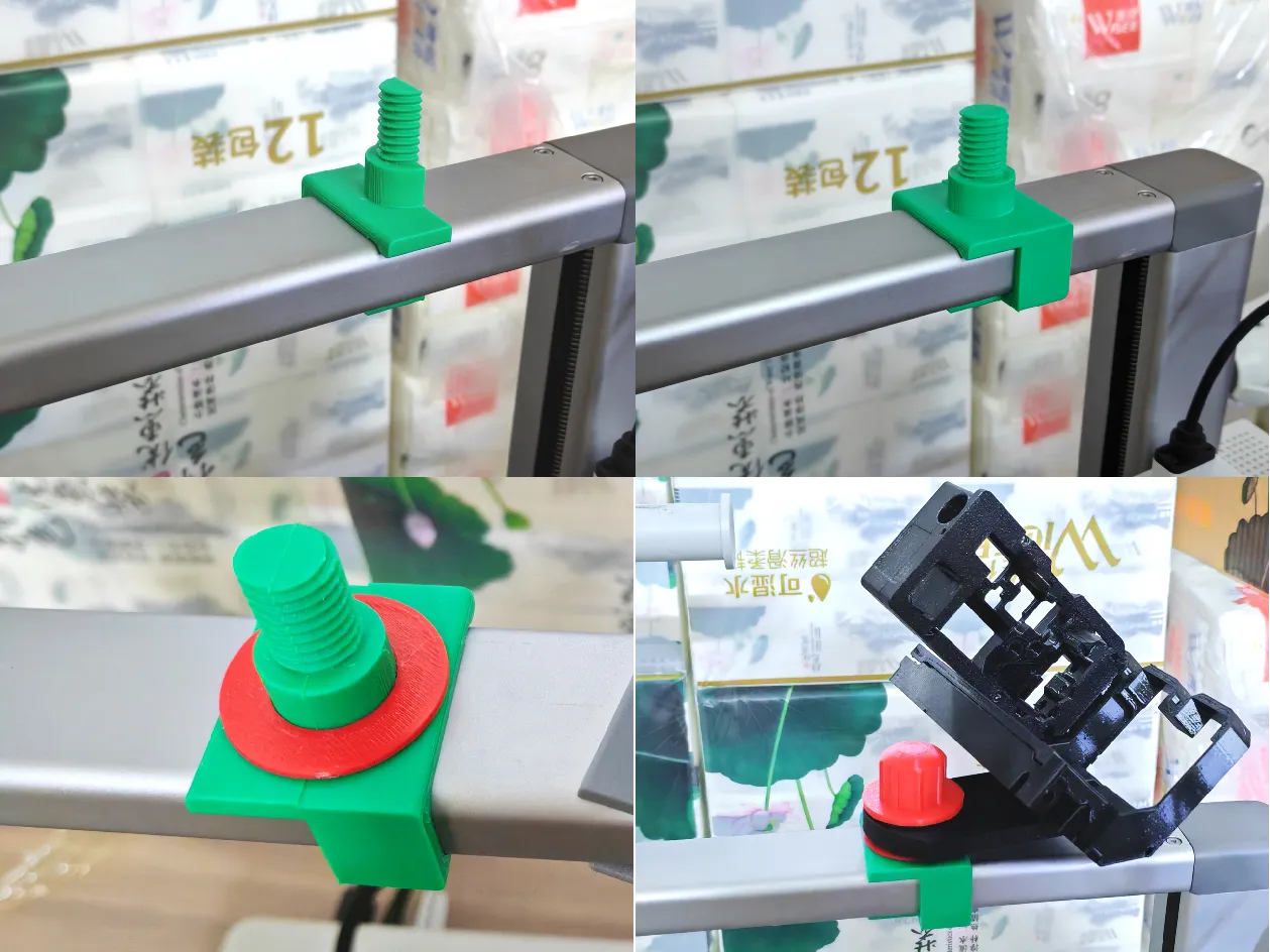
A1 (Those replacing from the first version to the second can skip step 1):
1.Clip the two separate stand parts into the beam from front to back, aligning them with the screws
2.Refer to steps 3-7 of the A1 mini assembly instructions above
Note:
The old 130 motor version and the initial 370 motor version of the bmcu can be printed with the original profile, meaning the print profile specifies the 130 version. For the new 370 motor version, use the 370 version print profile specified in the profile details. If you printed the 130 version profile and found the holes do not align, you can directly print the shell sleeve of profile 3 for replacement; other printed parts do not need to be replaced.
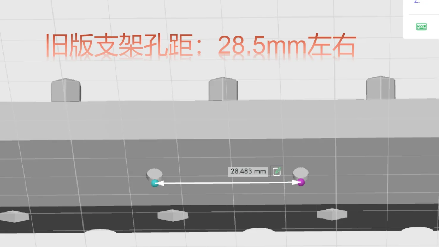
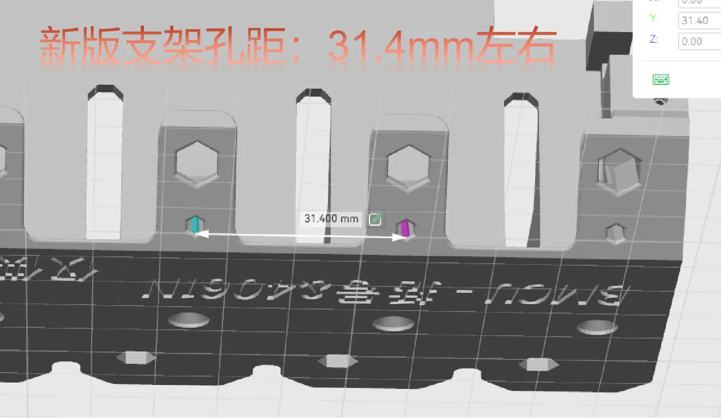
How to distinguish which stand shell sleeve is suitable for your bmcu base? The hole spacing of the stands is marked here, you can compare them to print the corresponding profile. Among them, the stand hole spacing for the old 130 motor version and the initial 370 motor version is about 28.5mm, and the mounting screws are M3*10 ordinary screws + M3 nuts. The stand hole spacing for the new 370 motor version is about 31.4mm, and the mounting screws are M3*14 self-tapping screws. Below are images of the stand base hole positions for your reference.
Boost Me (for free)
If you like it, please boost me, thank you!
License

You shall not share, sub-license, sell, rent, host, transfer, or distribute in any way the digital or 3D printed versions of this object, nor any other derivative work of this object in its digital or physical format (including - but not limited to - remixes of this object, and hosting on other digital platforms). The objects may not be used without permission in any way whatsoever in which you charge money, or collect fees.


Comment & Rating (73)