
Paint Spinner - aka "vortex mixer"
Print Profile(3)

Description
---
Customizable PegsV2 (beta): https://makerworld.com/en/models/2582657-paintspinner-pegsv2-beta
---




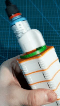
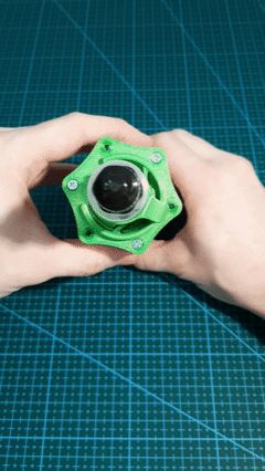
PaintSpinner or rather a manual vortex mixer for your paints.
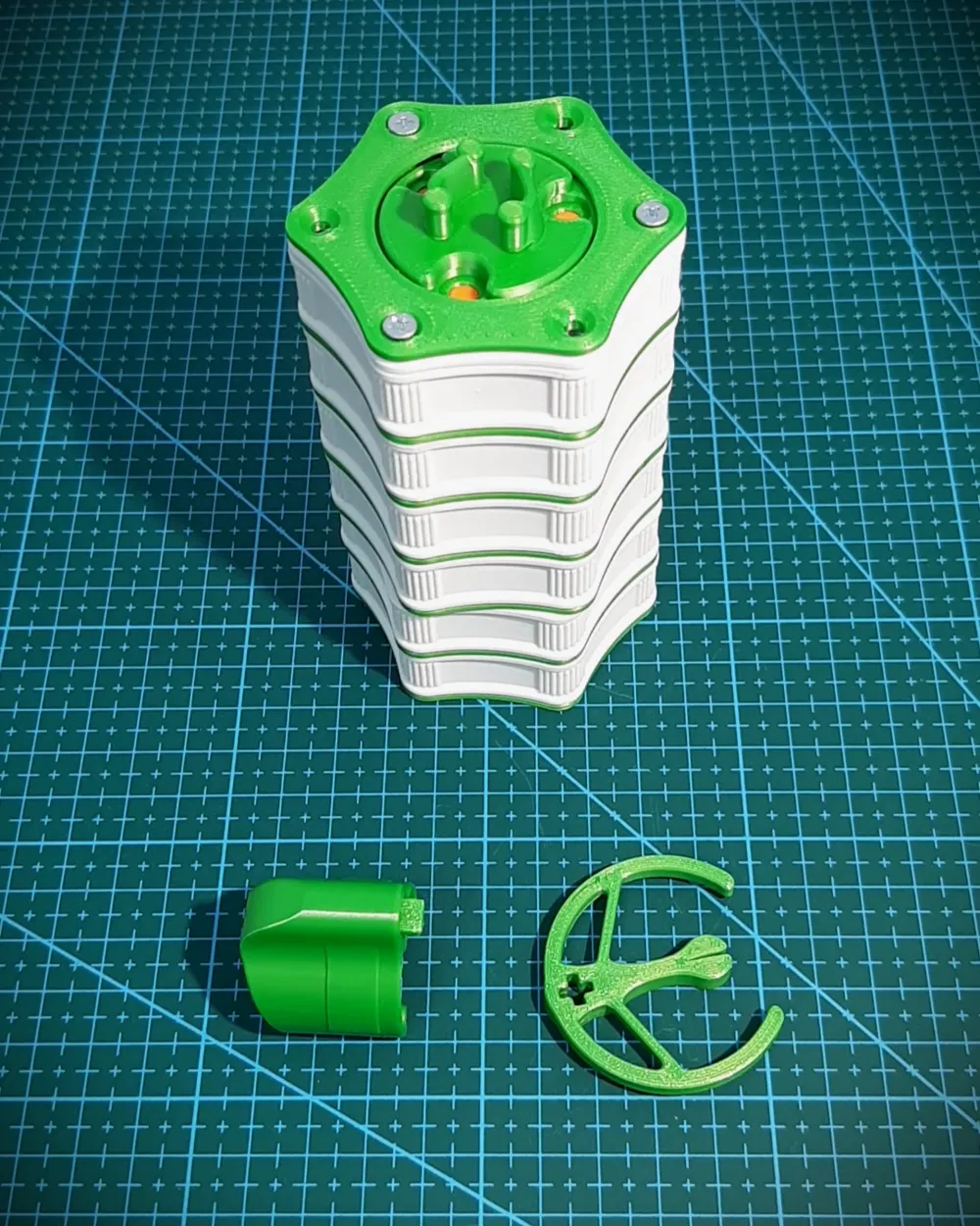


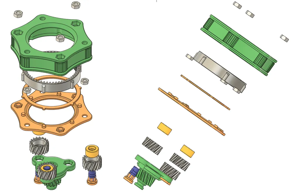
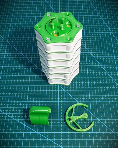

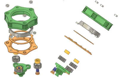
Basically it's a modular planetary gearbox with a clamp on top that holds a bottle (or jar) of paint.
It comes with two clamp variants - small for bottles (Army Painter, Vallejo and so on), and large for jars (Citadel, small jars).
Compared to actual vortex mixers the PaintSpinner mainly spins (duh) the paints, and does less shaking. And it's louder than burshless motored devices. The enclosed build and (lubricated) helical gears help with that, but it's better to use it at arms length from ones ears.
Sure a regular massage gun is good enough mixer, but I wanted something smaller that can always sit on the desk, next to the paints - has small enough footpring and it's easy and fast to use.
Nevertheless, it seems to work well enough and mix even strongly separated paints that've been sitting on a shelf a bit too long.
As far as I've been using it (since earlier prototypes) it comes in handy.


And this version of the clamp holds bottles nice and snug - so it's less likely that a mixed paint ends up thrown to the orbit…
Oldham Upgrade
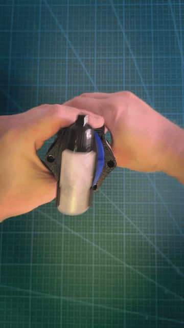
Introduces a new way to spin and shake paint bottles. Inspired by solution used in scroll compressors, where constrained rotation changes it to orbiting movement:

In our case it should add more "shake" to the bottle "spinning".

Also it has smaller footprint and works better than other mechanism (while making way less noise).
This solution will work best with dropper bottles and they should be laid on side. Anything too heavy or big will make operating the mechanism too hard.
__  ___
___  __
__
---
Updates:
- 28.03.2026 PegsV2 (beta)
- New variant of the pegs and bearings, that should be stronger and less likely to brake:
- This comes as customizable model, and few crucial tolerances can be adjusted.
- V2 variant requires filament strand to lock them in sun gear shaft slots
- As they print horizontally the bearings might spin differently (they need a minute or two before become smooth. If no - see customization)
- This change only requires reprinting pegs, bearings and caps. New pegs require sun gear shaft with filament holes in slots (ie. v1.4.0). Other components are compatible.
- 05.03.2026 (v1.4.0)
- Oldham upgrade - a new spinning/shaking mechanism
- DoubleHelical gears - are surprisingly quiet and avoid issues caused by axial forces pushing the gears up and down as they spin, causing locks.
- Slightly modified the SunShaft and Pegs - by including a small hole cutting through, that we can put filament in, preventing loose pegs from falling out too easily.
- Slight tweaks to dimensions here and there to improve fit and help the gearbox run better.
- 09.11.2025 (v1.3.2)
- added Reinforced Clip model.
- added new ShaftGear with raised shaft collar.
- updated Clamp features to V3 rebuild.
- created variant that can be mounted to a desk- https://makerworld.com/en/models/1976530-angular-paintspinner-vortex-mixer
- 05.09.2025 (v1.3.1)
- Created additional variants of pegs models, with different sized holes (3.25mm - 1.5mm) which can be reinforced with a short screw or any kind of short rod (steel, aluminium florist wire, maybe even a toothpick). Based on @maurice.beckman solution :)
- These are included in the main profile as well as in separate one - there's only a single copy of each model with different diameter in the file, so they have to be manually copy-pasted.
- Still I invite anyone with this issue to try different filaments (even individual spools of PLA from the same manufacturer after printing can behave differently under load (sometimes it's because additives like color and who knows what else) (best option: plastic is bendy and deforms before braking; bad: crumbly and brakes without much deformation)
- Created additional variants of pegs models, with different sized holes (3.25mm - 1.5mm) which can be reinforced with a short screw or any kind of short rod (steel, aluminium florist wire, maybe even a toothpick). Based on @maurice.beckman solution :)
- v1.3
- Created additional clip (ClampClip) that links Clamp and HolderInsert together, reinforcing it from forces pushing clamp sideways.
- (isn't backward compatible and requires new updated models of Clamp and HolderInsert)
- Added multiple sizes of Clamps - 24mm, 26mm, 28mm, 30mm, 32mm
- Created additional clip (ClampClip) that links Clamp and HolderInsert together, reinforcing it from forces pushing clamp sideways.
- v1.2
- New improved design of planet gears - now they have slightly rounded edges.
- This reduces dragging issues and as such the sand paper smoothing can be skipped altogether.
- Similarly shaft and helical ring had their gears teeth slightly chamfered.
- Updated assembly guide, refactored the instructions, and applied nicer formatting.
- Added assembly overview video.
- New improved design of planet gears - now they have slightly rounded edges.
---
Please mind, that this build can be a bit annoying (but since v1.4.0 slightly less).
Mainly because how small some tolerances are and how differently each filament can behave after printing.
Even a good build requires some extra time to "break in" the gearbox. Meaning it can be somehow stiff in the begginning with tendency to lock up (especially when turned clockwise).
To alleviate that, use lubricating oil (like the one for y-axis), and spin the gearbox part only counterclockwise (after a while clockwise should unlock itself).
Since planet gears got redesign the sand paper might be skipped, but if the assembly shows some resistance you can still try smoothing the top faces of the gears with high grid sandpaper.
If the lock occurs, do not force rotation (you might brake the bottom shaft). Instead manually rotate the topCap (or cap with paint bottle mounted) untill it's no longer stuck and rotates freely.
As the gearbox brakes in, it should be even possible to rotate the assembly with a single hand.
The main build uses printed bearings, but it's also possible to use actual ball bearings instead - 623 (3x10x4 mm).
Traits:
- modular
- perishable parts (like gears) can be reprinted individually, separate from chasis
- planetary gearbox
- gears ratio: YES
- mixes paints: YES
- printable bearings: YUP
- ball bearings: sure, why not
Hardware:
| Part | Amount |
|---|---|
| M3 30mm screw | 12 |
| M3 20mm screw | 3 |
| M3 16mm (or 20mm) screw | 6 |
| M3 nuts | ~36 |
-* all screws heads must have countersunk heads
| Useful tools | |
|---|---|
| Lubricant (oil or silicon grease) | Strongly recommended. For example like the one used to grease y-axis |
| Silicon/felt self adhesive feet | |
| pliers | |
| screwdriver |
(Ball bearing variant hardware is listed in the assembly doc)
General notes:
NOTE: All prints were designed and tested with 0.4mm nozzle. I would be carefull with anything else to keep the correct dimensional accuracy.
NOTE: This assembly might extra time to work most optimally. Make sure none of geared parts (HelicalRing, Planet Gears, Shafts) are deformed when you take them off the print bed.
(optional but helpful if the assembly shows resistance) Use high grit sand paper to smooth out planetary gears top face (with thin sides).
Lubricate each module after assembly and verify the mechanism rotates effortlessly.
NOTE: For the gears use material that's more likely to deform than break (ie. creep slowly than fail abruptly).
PETG seems to work nice in that regard, plus it's more resistant to temperature (which will rise if we spin the mechanism too intensely).
Other than that even regular PLA can have different properties in that regard depending on the manufacturing process or even color addittives used.
In general the gears should be fine printed with whatever but it makes more sense to use tougher and less brittle filament.
Or use whatever actually prints out well and allows each module to rotate freely.
NOTE: Because of the shape of the gears (ie. helical) as you rotate the mechanism, it'll cause the planets and shafts to travel slightly upwards (spins clockwise) or downwards (spins counterclockwise).
Usually the counterclockwise spin requires less effort on freshly assembled gearbox. But after playing around with it for a while, all gears should begin to break in and operate more and more smoothly. At some point it should achieve state when spinning in either direction is effortless.
Similarly it will behave differently without mount installed, and with paint bottle clamped in. It's advisable to use it with bottle of paint. Especially while doing clockwise spin - the weight of the paint will push the gears shaft assembly downwards.
NOTE: All gears (planet gears, helicalRing, shaft) might be better when printed on 0.16mm layer height. Compared to 0.20mm it doesn't take that much more time but also makes each layer slightly smaller - which seems to help gears run more smoohtly and there's less to grind down as they're in use.
Parts like bearings might not work correctly when printed in 0.16mm layer height. At least during some of my tests these kind of pegs and bearings didn't work as well as ones printed in 0.20mm layer height.
Test prints:
It might be best to start with few test prints. It'll help to find out which filaments works best for small tolerance assemblies like bearings.
Suggested steps are:
- print peg and bearing -> test whether bearing spins freely around the peg
- print shaft, the other 2 pegs/bearings, gears and helicalRing - and test how easily they fit together.
- print chassis module
- and repeat tests from step 2. but with helicalRing inserted in the chassis. This might contract the ring a little and change the assembly fit.
- planet gears might drag and scratch a little on the chassis lip, if they do use high grit sand paper and smooth gears top faces.
- make sure the M3 nuts can make a tight fit into the chassis without falling out
- if they do it's isn't a deal braker, they can be locked in place with a bit glue or bluetack, or use soldering iron and press the in (like brass inserts).
Toughness
- If you're not sure which filament from your collection has best mechanical properties (ie. it rather deforms and bends rather crumble and delaminates on layers under load) - try printing test pegs or even gear shafts.
- eg. 3 pegs of each type, which then try braking in half with pair of pliers and notice which posed most resistance
- similarly with gear shaft (though it's more expensive print than pegs), test how hard is to brake off the gear part from the plate.
- correctly printed (see boolean reinforcement from main profile, described below) should sooner result in broken plate than gear snapping off at any point.
- If that's not the case try different filament or make sure to dry the one you chosen.
---
Mind that print profile includes extra parts in some models. Mainly:
- Shaft, has embedded modifiers with higher amount of walls, which results in extra material used to reinforce the print. It's advisable to keep them as is.
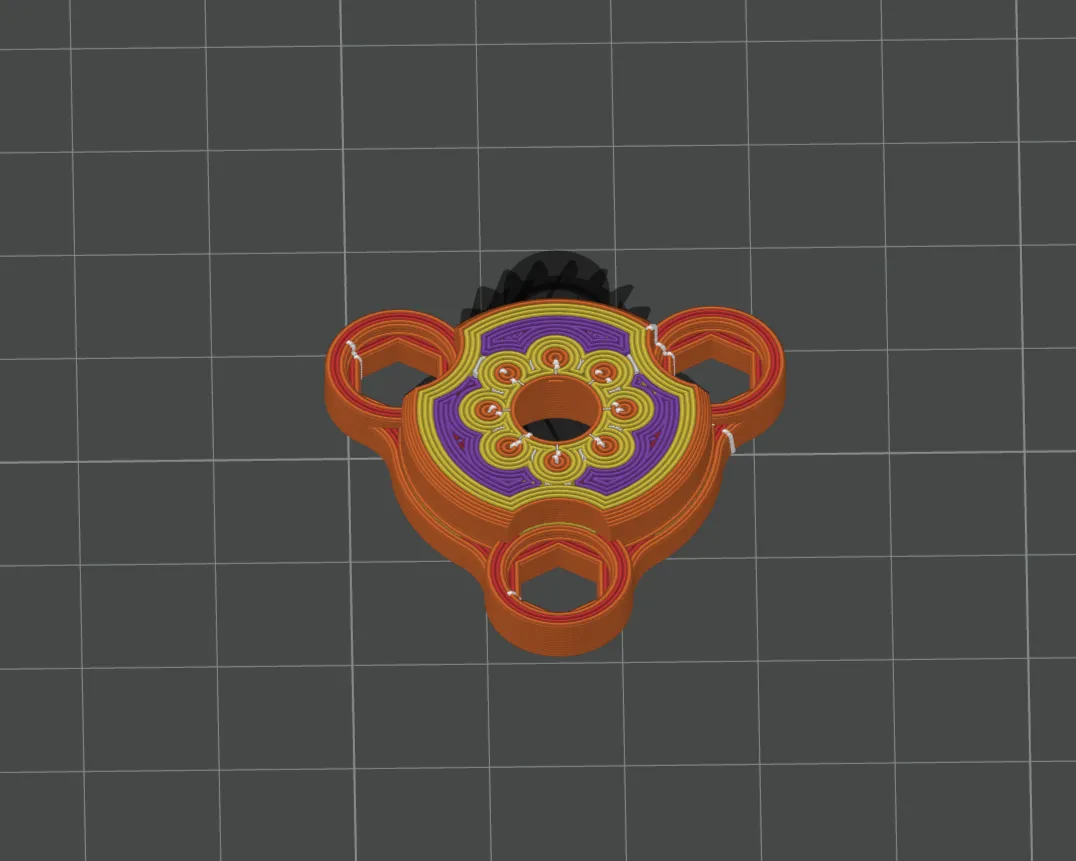
- Another trick is to use "Concentric" top surface pattern - it provides much better adhesion between shaft gear and plate. Even without internal supports. Printing it with monotonic line will result in a gear shaft that can be easily twisted off.
- TIP: creating an intermediary island / foot with a sligth skewed face, between the shaft gear and plate improved the connectivity. Instead having gear teeth lie flatly on the plate, they're embedded in extra material for next 4 layers. This helped increase connecting surface.
- After these tweaks in my experience it's much, much harder to brake off the gear shaft. Compared to the original without the boolean reinforcements, while using two pliers to brake the model, instead snapping off the gear it's more likely to deform and destroy the plate and entire thing, before it get even close to braking off.
- If that's not the case in your print that might be difference between choice of filament or how dry it is - I've used PETG for the gear shaft and had to dry it intensively in order to get the best result. PLA will likely differ from spool to spool (some colors (thanks to various additives during manufactuing) seem to be better than others)- the goal is to use one that after pritning tends to deform before braking instead crumbly ones that are easy to snap off. Sometimes it's a matter of experimenting and finding out which one in our collection has best mechanical parameters after printing.
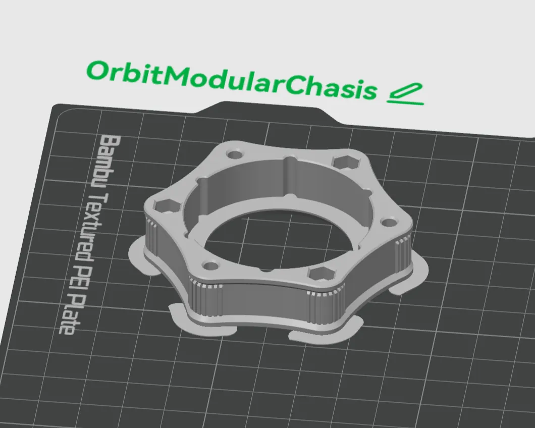
- OritModularChasis comes with custom "ears" in corners, that prevents them from lifitng. You can try printing without them - this way it's easier to fit all of required parts on single plate (on A1 mini).
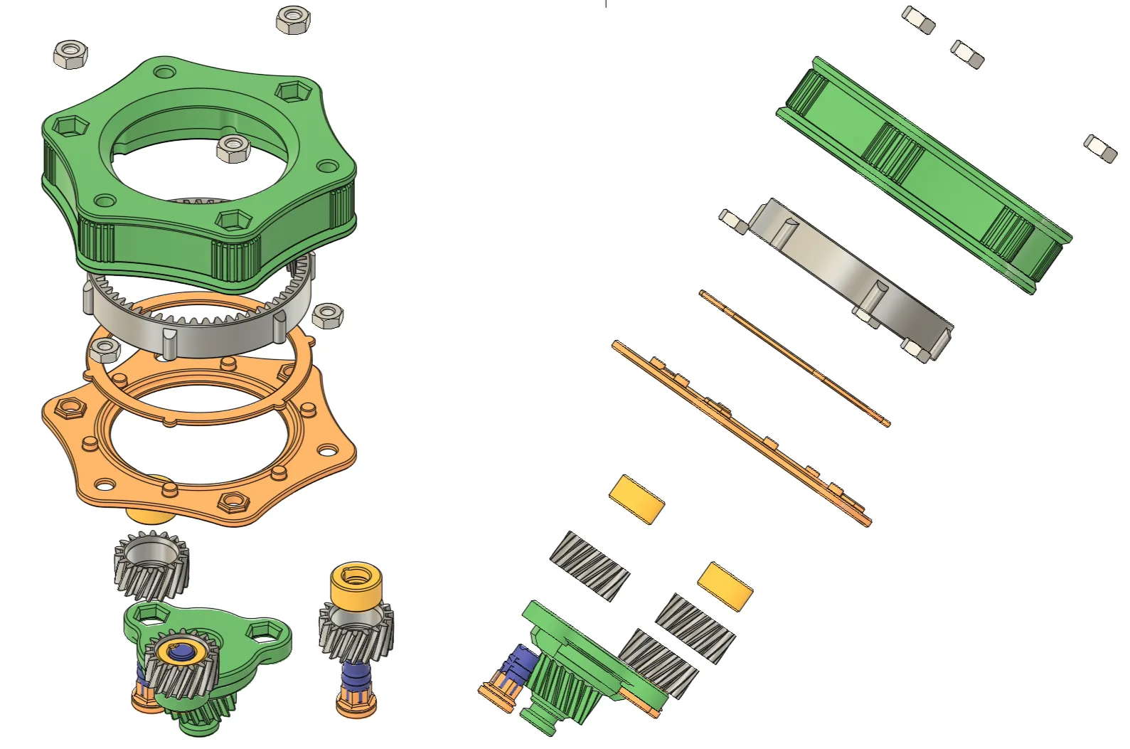
See the assembly guide PDF in the attached files.
Or video:
Previous version:
Documentation (1)
License



Comment & Rating (64)