S.T.A.L.K.E.R 2 Scanner M


Print Profile(1)

Bill of Materials
- M6 Threaded Insert x 6: ~15mm deep (leg connectors)
- M5 Threaded insert x 3: ~10mm deep (leg bottom)
- M6 Bolt x 6: 30mm long
- M5 bolt x 3: 30mm long
Description
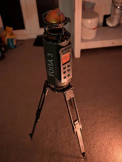
This is a model of the STALKER 2 artifact scanner device. It should be 1:1 scale (see “printing at a smaller scale” below) based on some guesswork of the sizing of components. In principle it could also be printed at a smaller scale but I'm not sure all the tollerances would still fit with FDM.
The only parts which are not pritable are the various nylon straps used for the sling, and the wires that run around the copper dome at the top, and some M5/M6 threaded-inserts + bolts.
There is an attached guide that should indicate how to connect the pieces.
NOTE: This is a very large model. It takes several days to print and paint (also probably more than 1kg of filament). I modified the files while building it to resolve any issues so if anything doesn't work quite right, the .obj file is attached so you can make a new part.
Painting
There are a lot of screenshots attached which should give an idea of how to paint the various parts. I would reccomend:
- Prime the whole thing black.
- Drybrush any steel parts with silver paint.
- Paint the copper parts with copper metallic paint.
- The control box as well as a couple of other areas are a red-ish colour. This seems close to red-oxide primer.
- The body of the scanner is a sort of olive drab military paint.
Non-printed parts
Legs
The pipes used for the legs have a 15mm outer diameter. This is the same size as a regular gas/water pipe used in the UK. These would be a more durable option than printed tubes.
M5 (10mm deep) & M6 (~15mm deep) threaded inserts are required.
This sort:

Also the corrisponding bolts
- M6 ~30mm
- M5 ~30mm
The legs are a little problematic because the original model doesn't contain any mechanism to retain them. They rely on friction. This is why it uses bolts and inserts.
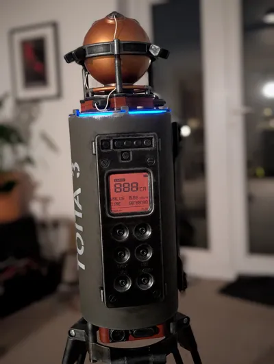
Wires
The 3 wires connected to the plugs at the top of the model are roughly 19cm long, 1-2mm tall and ideally 4mm wide (they are two core wires in the game). They are white/off-white. Personally I used single core wire as it's all I had on hand. The wires are just glued in at both ends.
Another option would be to print wires in white TPU (or just use a pice of TPU filament).

Printing at a smaller scale
I have not tested this at a smaller scale. I think the tolerances etc. are big enough that it might work down to 50% size or so, but it would be better to open the .obj and resize the model, then check for any walls that are too thin and increase the tolerances.
Possible Improvements
 | The lights on the front of the device could be printed in coloured, transparent PETG and illuminated from behind. |
 | The screen could be illuminated from behind or use a real LCD (maybe it could show weather data or something). |
 | Instead of the copper ball at the top, a plasma ball could be used instead. It would just require a minor re-design of the top base.
Around the ball at the top there are little LED lights, that I didn't put much detail into. Tetter ones that actually light up could be designed instead (although I think they'd need to be larger). |
 | The strap rings were designed to fit a ~32mm nylon strap which could easily be added (or maybe printed in TPU) |
Changelog
- Fixed error in stencil letter spacing.
- Added .step file
Comment & Rating (8)