Search models, users, collections, and posts

3D Print Guitar
IP Report


Print Profile(1)

0.2mm layer, 2 walls, 15% infill
Designer
39.1 h
6 plates
Open in Bambu Studio
Boost
235
538
7
4
401
37
Released
Bill of Materials
Bambu Filaments
Select all

Description
Content has been automatically translated.
I. Raw Materials and Tool Preparation
1. 3D printing filament
- Main Material (ABS Black): Used for the core load-bearing structure of the guitar body. ABS has good sandability, polishability, and heat resistance, but warpage during printing should be noted
- Decorative Material (PETG Color): Used for pickguards, knobs, or non-load-bearing inlays. PETG has good toughness and strong layer adhesion, making it suitable for cosmetic parts
2. Hardware and Electronic Components (Salvaged/Purchased Parts)
- Wooden Neck: Includes a complete fretboard, frets, and headstock. This is crucial for ensuring accurate intonation and feel; 3D printed necks indeed have insufficient tensile strength and creep risk, so using a wooden one is the correct choice
- Bridge System: Fixed Bridge (Hardtail) or Tremolo Bridge
- Circuit System: Pickups, Potentiometers (Volume/Tone), Gear Selector Switch, 6.35mm Output Jack
- Shielding Material: Conductive copper foil tape or conductive paint (because plastic guitar bodies lack electromagnetic shielding)
3. Assembly Supplies
- Adhesive: 302 Modified Acrylate Adhesive (i.e., 302AB adhesive). This adhesive has high curing hardness, good aging resistance, and is suitable for bonding ABS
- Fasteners:
- M4 self-tapping screws: Used for connecting the neck to the body
- M3 self-tapping screws or heat-set inserts: Used for securing the pickguard and back cover
- Auxiliary Tools: Strong Zip Ties, F-clamps or C-clamps, Sandpaper (200-800 grit), various thicknesses of paper or sandpaper pieces (for shims)
II. Core Slicing Parameter Settings
To withstand a string tension of approximately 40-80kg, slicing parameters must be optimized for strength
- Wall Thickness (Perimeters/Walls): Most critical parameter. Guitar body shell is recommended to be set to 6+ walls. Compared to infill percentage, increasing wall thickness significantly improves bending rigidity
- Infill:
- Overall infill percentage: 40% - 50%. (I used a higher infill percentage to balance the weight)
- Infill pattern: Recommended Gyroid or Honeycomb
- Local reinforcement: Around the neck pocket and bridge mounting holes, a modifier must be used to set the infill percentage to 100% solid to prevent screw stress points from collapsing
- Top/Bottom Layers: 5+ layers to ensure surface flatness and facilitate bonding
III. Production and Assembly Notes
1. Body Bonding and Anti-Creep Treatment
- Surface Treatment: ABS and PETG surfaces are smooth, resulting in poor adhesion when applying adhesive directly. Before applying 302AB adhesive, both contact surfaces must be roughened with coarse sandpaper (200 grit) and cleaned of dust
- Pressurized Curing: After applying adhesive, use zip ties or F-clamps to firmly secure the bonded parts. Key Point: Although the adhesive instructions state curing in a few hours, for a guitar body subjected to continuous tension, it is recommended to let it rest for 24-48 hours to ensure the chemical reaction is completely thorough
- Anti-Sagging: 302 adhesive has strong flowability; when bonding, be careful to protect the front appearance, and any overflowing adhesive must be wiped off before it cures
2. Neck Installation and Angle Adjustment (Shimming)
- Align Centerline: Neck installation is critical for success. Ensure the neck's centerline strictly aligns with the bridge's centerline, otherwise, at higher frets, the strings will deviate from the fretboard
- Shim Adjustment (Shimming):
- Phenomenon: Due to 3D printing shrinkage errors, string action might be too high (even with the bridge lowered all the way) or too low after neck installation
- Operation: As described, use small squares cut from paper or sandpaper, placing them in the neck pocket either towards the inner or outer side of the body to change the neck pitch
- Principle: Fine-tune the angle. Shimming on the headstock side will raise the string action; shimming on the bridge side will lower the string action
3. Circuit (Circuit)
- Wiring for the circuit can be referred to in the image below; I learned the wiring method from this article: https://www.bilibili.com/opus/859024073731080197?spm_id_from=333.1387.0.0
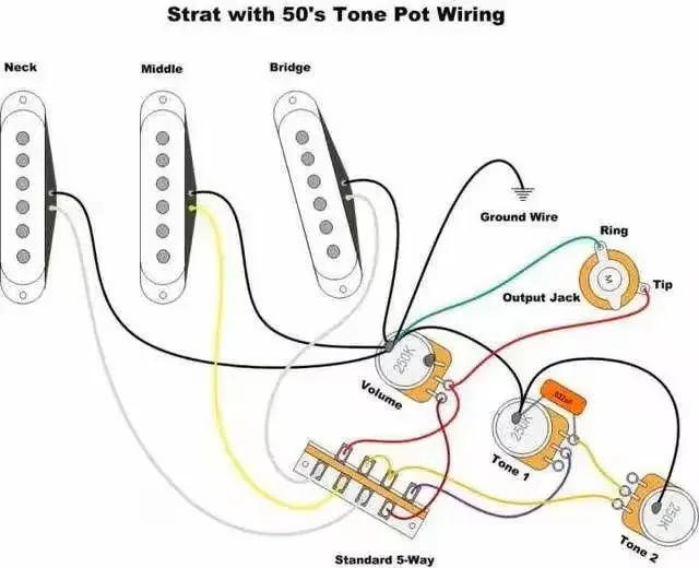
- Faraday Cage Construction: Both wood and plastic are insulators. You must line the inner walls of the circuit cavities (pickup cavities, control cavity) with conductive copper foil, ensuring all foil pieces are connected to each other
- Bridge Grounding: Extremely important. FDM materials are insulating; you need to specifically run a ground wire under the metal base of the bridge and connect it to the common ground point of the circuit system (usually the volume potentiometer casing). Otherwise, there will be significant hum when your hand leaves the strings
4. String Installation and Stress Testing
- Step-by-step Stringing: Do not tighten all strings to standard pitch all at once
- First, install all strings and slightly tension them
- Observe the body joints for cracks or deformation (Creep)
- Once confirmed, gradually raise the pitch to standard tuning (E-A-D-G-B-E)
I don't really want to disassemble the guitar to take pictures of the corresponding steps anymore. If it breaks and I have to remake a component, I will add these corresponding steps then:(
License

This user content is licensed under a
Creative Commons Attribution


Comment & Rating (7)