Ultralight Glider glider


Print Profile(1)

Description
Third Edition: The Best Low-Resistance Glider Currently Available
Without further ado, let's get right to it.
If the app cannot be opened, you can use the web version.
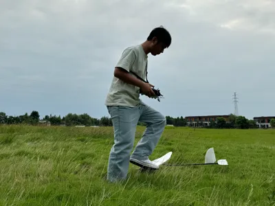
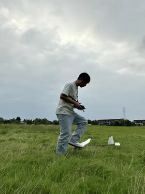
Unpowered throw test video: [Third Edition DIY Glider Unpowered Hand-Throw Test] https://www.bilibili.com/video/BV1U8RfYfEZR/?share_source=copy_web&vd_source=77c4d2568a8afa1ad8058ebcf82c9fed
Flight video: [Third Version of Homemade Glider Flight Test, Happy Ending] https://www.bilibili.com/video/BV1S8RfYfE7R/?share_source=copy_web&vd_source=77c4d2568a8afa1ad8058ebcf82c9fed
Recommended to use PETG printing
Please read this entire document before assembling!!!
Please read this entire document before assembling!!!
Please read this entire document before assembling!!!
Features
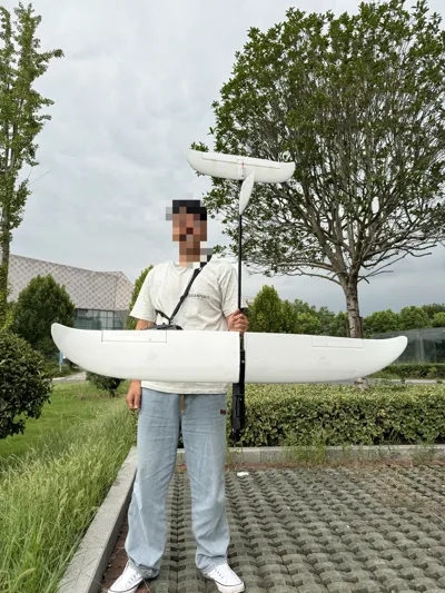
1. The fuselage has a streamlined design with minimal aerodynamic drag;
2. The entire aircraft is fully modular with quick-release components, allowing it to be packed into a 90x25x10 cm bag;
3. The body is printed using PETG, ensuring both strength and flexibility;
4. Ideal for model enthusiasts who enjoy DLG;
5. For aggressive flight, insert a 1mm carbon rod into the horizontal tail wing for reinforcement, as shown in the image following the article;
Assembly
1. The body is divided into two sections: the front section and the rear section. The front section houses the motor, while the rear section houses the servo and aileron connectors. First, install the two M3 nuts from the rear side, using the aileron quick-release clamp for auxiliary positioning; then tighten the M3 x 40mm screws. Once the nuts are fully secured, remove the quick-release clamp;

2. There are alignment holes (red) at the connection between the front and rear sections. Use a disposable thin rod (recommended diameter below 1mm) for alignment, then bond with AB glue or 502 adhesive. Cover with masking tape and wait for the adhesive to cure;

3. Install the servo in the rear section. Install the servo first, then the linkage rod. The receiver can be installed on the opposite side of the servo's deflection angle, secured to the fuselage wall with masking tape. Connect the aileron extension joint to the JST three-color connector terminals, apply 502 adhesive to secure them, and connect to the receiver;

4. Use a front-shaft motor, which reserves some space. Use a propeller clamp + folding propeller configuration, paired with a speed controller with a brake function, to achieve gliding. This canopy is compatible with Mayatech's alloy propeller clamp.

5. Use the wing and tail of the surfer model. The wing is attached to the quick-release clamp using EPP adhesive. There are 8mm pre-drilled holes (red) corresponding to the wing sleeve, and the remaining 3mm pre-drilled holes (white, not fully marked) can be used to attach the quick-release clamp directly to the wing using a screwdriver to drill holes. After drilling, insert a 3mm carbon rod and apply adhesive. Due to printing limitations, a 1mm carbon rod reinforcement hole (green) must be reserved on the quick-release clamp, secured with 502 adhesive, to accommodate load requirements during high-maneuverability operations;

6. The horizontal tail quick-release clamp also has reserved holes for securing the tail (as the blogger has experienced the tail detaching from the printed part during forceful rolls). Note: The central hole (red) is the tail tube positioning hole; do not insert a carbon rod for fixation. Additionally, all carbon rods must not obstruct the carbon tube from passing through this component;

7. Two types of hatch designs are provided: a direct hatch (red) and a modular hatch. The modular hatch has MT30 holes reserved for installing a 2S 450mAh battery;

Details
1. The rear hatch does not need to be permanently glued; simply attach it to the fuselage with masking tape for easy maintenance;

2. When installing the vertical tail fin, first insert the component into the carbon tube. Use nails or pen marks at the diagonal positions for alignment, then remove the component. Use a 3mm drill bit to drill opposing holes at the alignment points. Do not drill through in one go, as this can easily cause misalignment. It is recommended to drill one hole at a time, then use a carbon rod to secure the connection; Use EPP adhesive to attach the vertical tail fin to the carbon tube, and use 502 adhesive to secure the connection between the carbon rod and carbon tube. Reinsert the component into the carbon tube without securing it;

3. Adjust the component from the previous step to a position 2-3 cm behind the rear end of the vertical tail fin, then insert the horizontal tail fin into the carbon tube and align it for assembly. After aligning the horizontal and vertical stabilizers vertically, secure the components with 502 adhesive, then remove the horizontal stabilizer;
4. After the glue has dried, reattach the horizontal stabilizer. Use a pen or hard object to insert into the second hole of the horizontal stabilizer for positioning. Remove the horizontal stabilizer and drill a 3mm hole at the positioning point. Cut the carbon tube 2cm behind the hole;
5. Connect the carbon tube to the rear section of the fuselage, make minor adjustments to the appropriate angle, and secure with glue;
Note
This glider does not use traditional control rods for operation but instead uses a steel wire of approximately 0.3mm in diameter for pulling. A torsion spring or reverse spring is installed on the horizontal stabilizer for unidirectional reset. The servo pulls the steel wire, which resists the torsion spring to perform the work.
The following are some images for reference during installation:


Recommended configuration:
Motor: Front-mounted 2312 1150KV
Battery: Lipo 2S 450mAh or 3S 300mAh
ESC: Mainstream ESC, recommended 30A, with BEC and brake
Servo: Mainstream 9g servo
Receiver: Recommended with altitude feedback functionality
Boost Me (for free)
Creating these designs is no easy task; each finished product requires multiple revisions, improvements, and validations...
If you like my work or have any bold ideas, please leave me a message;
Your support is a great encouragement to me. Thank you.
License
You shall not share, sub-license, sell, rent, host, transfer, or distribute in any way the digital or 3D printed versions of this object, nor any other derivative work of this object in its digital or physical format (including - but not limited to - remixes of this object, and hosting on other digital platforms). The objects may not be used without permission in any way whatsoever in which you charge money, or collect fees.
Comment & Rating (3)