Pearity - 8-bay 10-inch mountable storage solution


Print Profile(2)


Bill of Materials


- Mini ITX/Flex ATX PSU 250W or above x 1:
- Oiyagai IEC320 C14 Power Inlet Module with Rocker Switch, 250V 10A Male Socket Plug, DPST x 1:
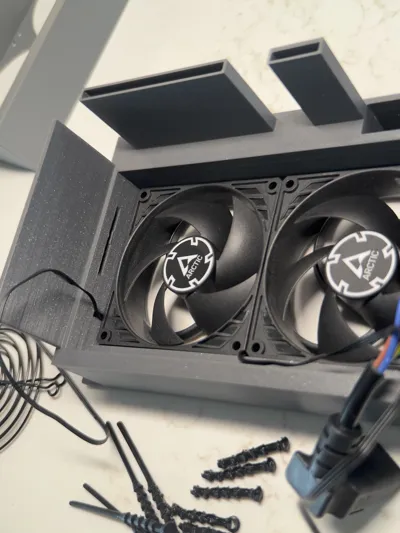
- Arctic P9 Silent 92mm PC fan x 2:
- Easycargo 4pcs 92mm fan grill guard x 1:
- Cerrxian 20cm 90 degrees IEC 320 c13 to c14 PDU cable x 1:
- IO Crest 8 port sata III to m.2 b+m key adapter pci-e 3.0 x2 x 1: only needed if using Thunderbolt
- Fantom Drives Extreme Thunderbolt 3 SSD m.2 enclosure x 1: only needed if using Thunderbolt
- Jonsbo N3 backplane x 1:
Description
READ BEFORE PRINTING!
This guide assumes a basic knowledge of electronics and electrostatic safety. I’m not responsible for any damage done to your drives!
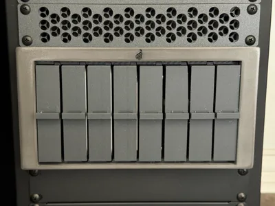
This is the Pearity, an 8-bay drive enclosure for 10 inch racks that uses a readily available backplane.
Designed to complement your homelab and fit on your mini-rack.
Boost Me (for free)
Think this is cool? Boost me for free!
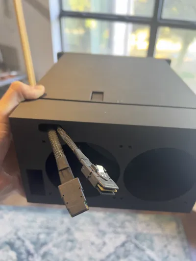
It can connect directly to a PC with mini-SAS cables coming out of the back OR use Thunderbolt 3 - via a Fantom Drives Extreme SSD enclosure with an IOTech m.2 to dual mini-SAS board.
It utilizes the backplane from the Jonsbo N3, available on aliexpress from many different sellers. Search for “server backplane 8 sas” or “jonsbo n3 backplane” on aliexpress and pick one of the black ones.
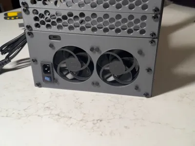
For power it uses a flex ATX PSU. I’m using a 400W PSU, I’d recommend a minimum of 200W. You can also connect it to an external power supply: it needs two PATA/IDE power and one SATA power.
Instructions:
There are three main pieces to print plus 8 drive caddies. Every part needs supports. The main body experiences the most stress followed by the back panel, so I recommend printing in a strong material; I used ASA-CF with HIPS as a support interface layer. For the caddies I used regular PLA, for the front panel I used metallic PLA.
First print the body, back panel, and caddies and check the fit.
The front panel is optional and for purely aesthetic purposes. I recommend waiting to attach it until after the main body is mounted to your rack as it can be difficult to remove from the body. I have included multiple file types for the front panel in case you want to modify it or design your own.
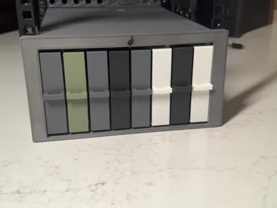
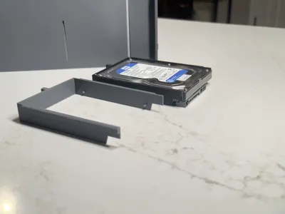
The drive caddies attach to drives with a press/snap fit.

Both 3.5in and 2.5in caddies are available.

Note: caddies are not designed for re-use between multiple drives, but if you are gentle you can use a pry tool to remove them and reuse them a few times.
Back Panel:
There are three versions of the back panel: one with rack ears at the very back for custom built racks; one with rack ears spaced 260mm from the front ears for 12U racks from Tecmojo and GeekPi; and one without rack ears.
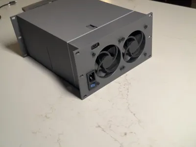
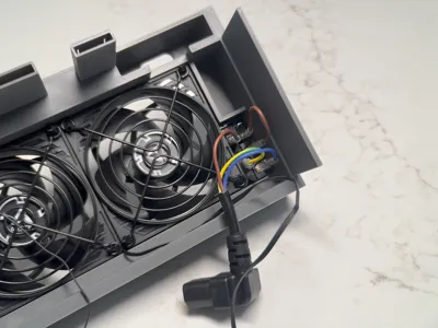
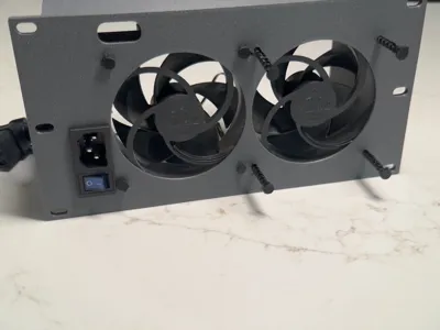
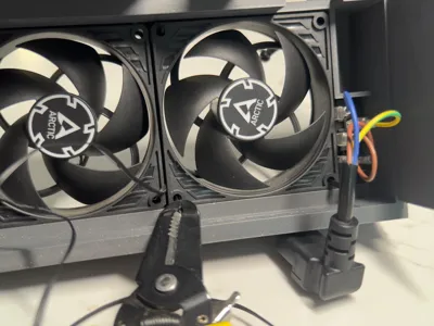
Place the fans in their places on the back panel, making sure airflow is going out the back.

Print the TPU fan mounts designed by im.jackharvest and thread them thru from the back side.

Make sure to attach fan covers to keep any cables from getting caught.

There are small channels to hold the fan cables to keep things neat.

The power plug inlet and switch pops into place on the back panel. Any plug the same size will work, it doesn’t need to be light up or colorful.

Strip the outer sheath of the power plug cable to its base. Cut and strip the wires and attach them to the back side of the plug inlet using the connectors. If you don’t know what connects where, google it before burning your house down.
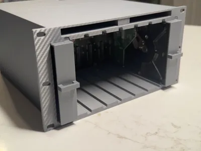
Main Body:
The backplane is 1mm longer than the interior width of the body, so fitting it in will be tight. I sanded off the extra mm, and while it makes the install easier, it isn't necessary. If you are going to sand the backplane wear appropriate PPE.

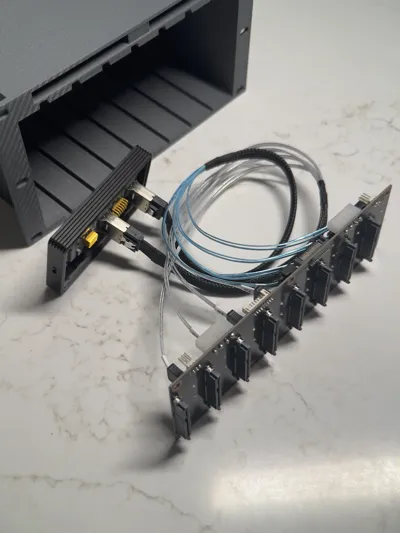
I recommend attaching the data cables to the back side of the backplane before putting it in place. If you want to connect using Thunderbolt I also recommend attaching the TB3 to SSD and m.2 to mini-SAS before installing the backplane.

There are cutouts to hold the backplane in place to avoid stressing the body. Once the backplane is in the cutouts, slide drives 1 and 8 slowly in while adjusting the backplane until they slide easily into their connectors.

If you’re using the Thunderbolt adapter it is easier to place it in the cutout in the back panel when attaching the back panel and body.

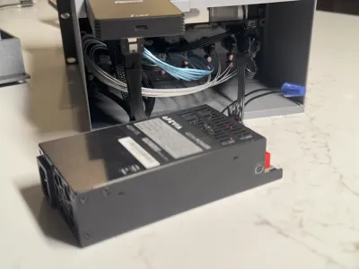
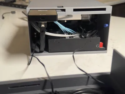
Connect the power supply to the backplane.

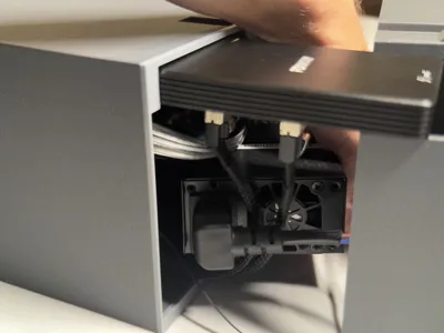
Connect the fan cables and place the PSU inside.

Check the clearance for all the cables one last time, then slide the back panel on.

Attach your Pearity to your rack.

Populate the Pearity.

Put the faceplate on and enjoy!
License
You may create derivative works based on this object, provided that all such derivative works are published exclusively on the MakerWorld platform and include proper attribution to the original creator. You may not share, upload, host, distribute, or publish this object—or any derivative work of this object—on any other digital platform, marketplace, or distribution channel. Commercial use of this object and any derivative works is strictly prohibited. This includes, but is not limited to, selling, renting, sublicensing, or using the object in any context in which you receive monetary compensation or other financial benefits.
Comment & Rating (26)