
Diy 3d printed CNC Machine

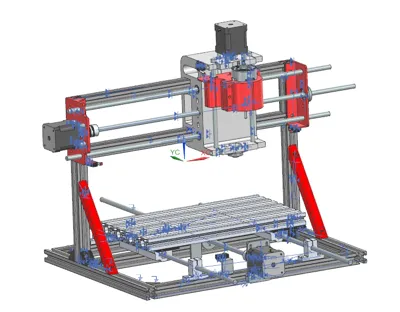
Print Profile(1)

Bill of Materials
- M4 SHCS Screw (length 6mm) x 60:
- M4 phillips screw round head (length 8mm) x 50:
- Washer for M4 screws x 100: Can be used for M4 as well as M3 screws
- M3 SHCS Screw (length 20mm) x 10:
- M5 SHCS Screw (length 14mm - 16mm) x 8:
- T slot nut (M4) for 2020 extrusions x 76:
- T slot nut (M5) for 2020 extrusions x 8:
- Washer for M5 screws x 8:
- M3 SHCS Screw (length 6mm) x 17:
- M4 SHCS Screw (length 8mm) x 6:
- M4 Nut x 6:
- 2020 aluminium extrusions (length 380mm) x 5:
- 2020 aluminium extrusions (length 340mm) x 2:
- 2020 aluminium extrusions (length 280mm) x 2:
- Nema 17 stepper motors x 3:
- 8mm lead screw end support bearing(KFL_08) x 2:
- 8mm lead screw end support bearing(KP_08) x 1:
- Limit Switches x 5:
- T8 Nuts for lead screw x 3:
- 8mm Lead screw 450mm (minimum) x 1:
- 8mm Lead screw 160mm (minimum) x 1:
- 8mm smooth rod 160mm (minimum) x 2:
- 8mm smooth rod 450mm (minimum) x 2:
- 8mm smooth rod 350mm (minimum) x 2:
- 8mm Lead screw 350mm (minimum) x 1:
- Linear Bearing 8mm long x 6:
- SC8LUU Linear bearing block 8mm x 4:
- 8mm smooth rod end supporr x 4:
- T8 lead screw nut x 3:
- Flexible stepper motor coupling 5mm to 8mm x 3:
- 2040 Aluminium Extrusions (300mm) x 4:
- RS-775 Motor x 1:
Description
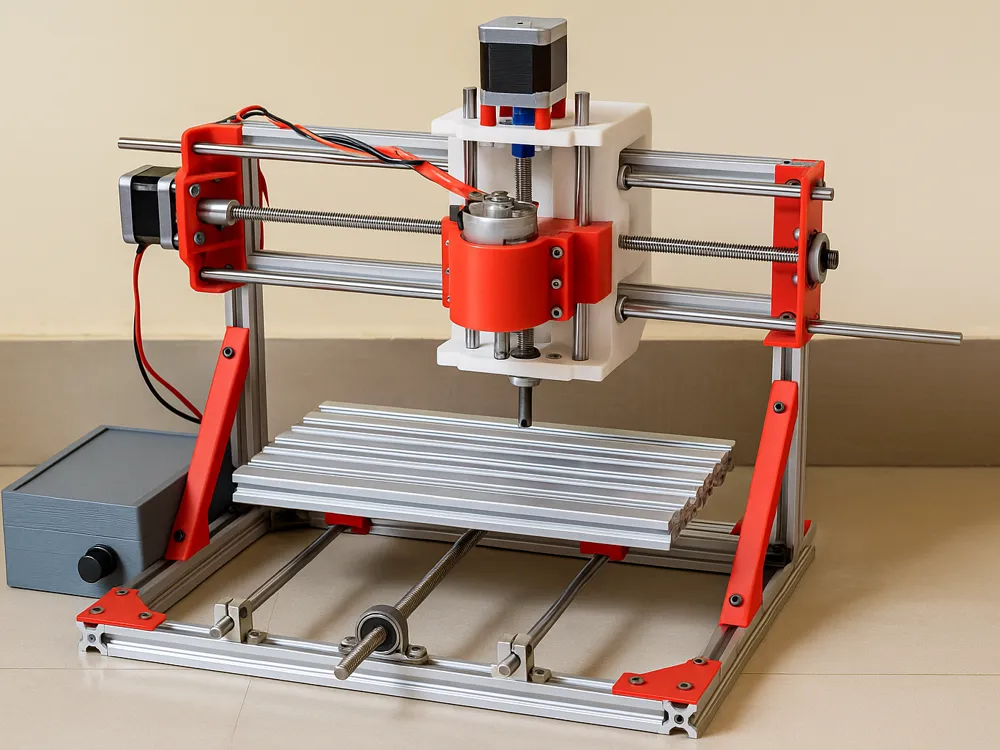
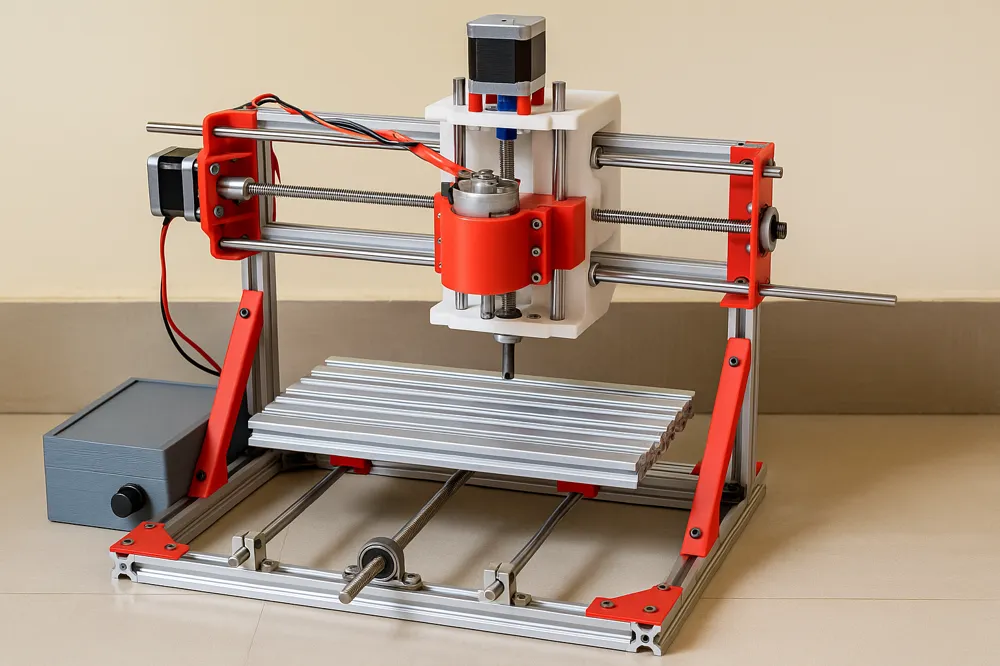
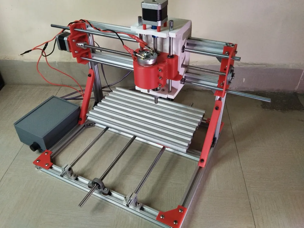
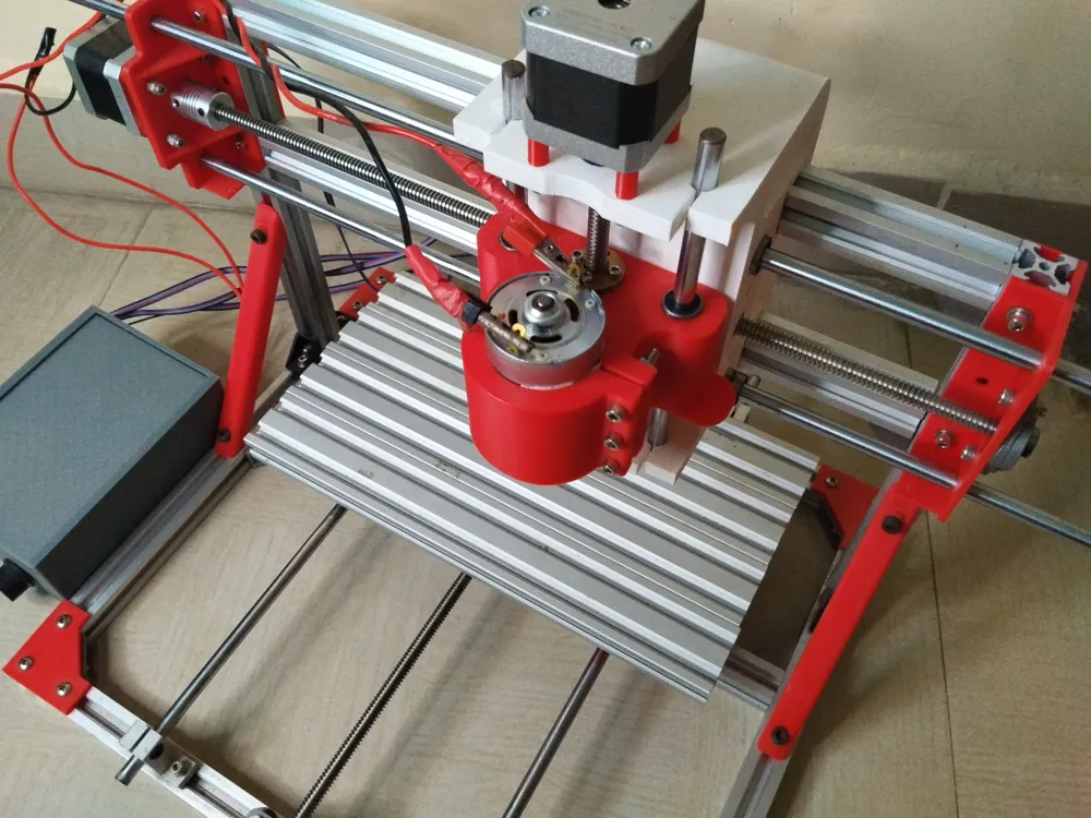
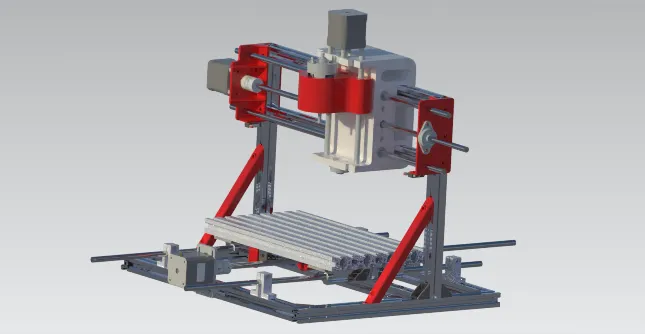
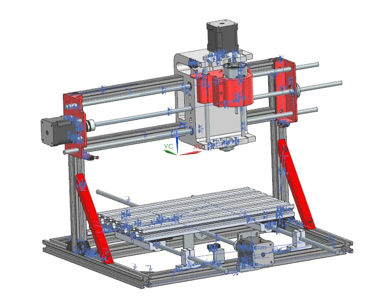
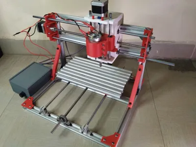
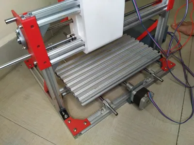
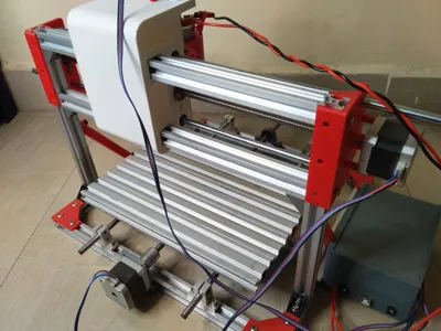
This is a 3d printed CNC Machine, it has a similar design philosophy as the generic 3018 machines.
It uses a mix of mechanical and 3d printed parts.
All the 3d printed parts are shared as STLs, and a Bambu Lab print file has also been been attached.
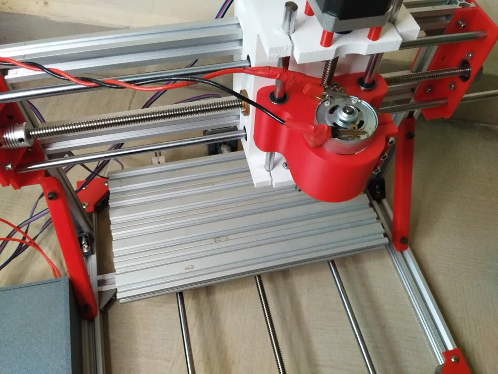
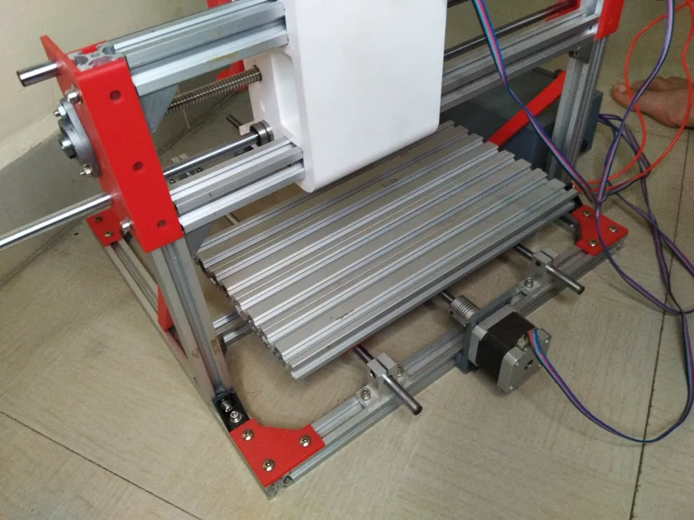
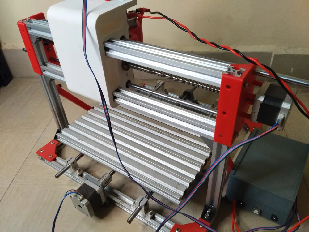
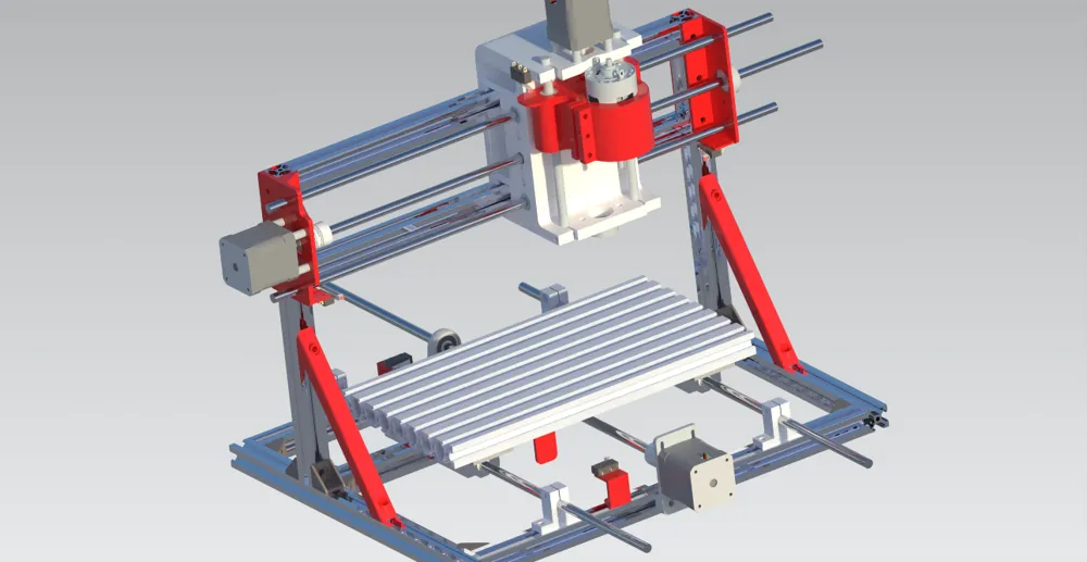
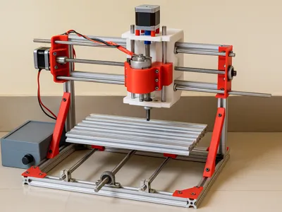
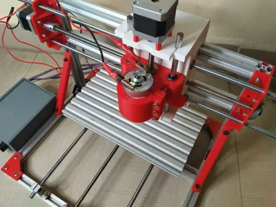
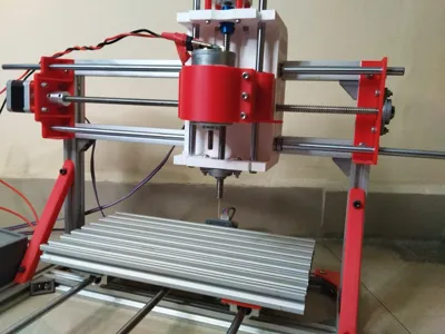
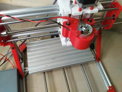
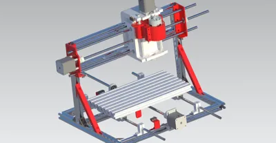
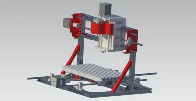
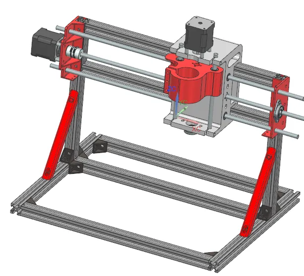
The picture of the Final assembly is shown below
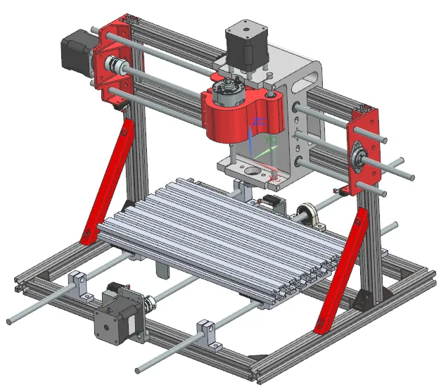
ASSEMBLY
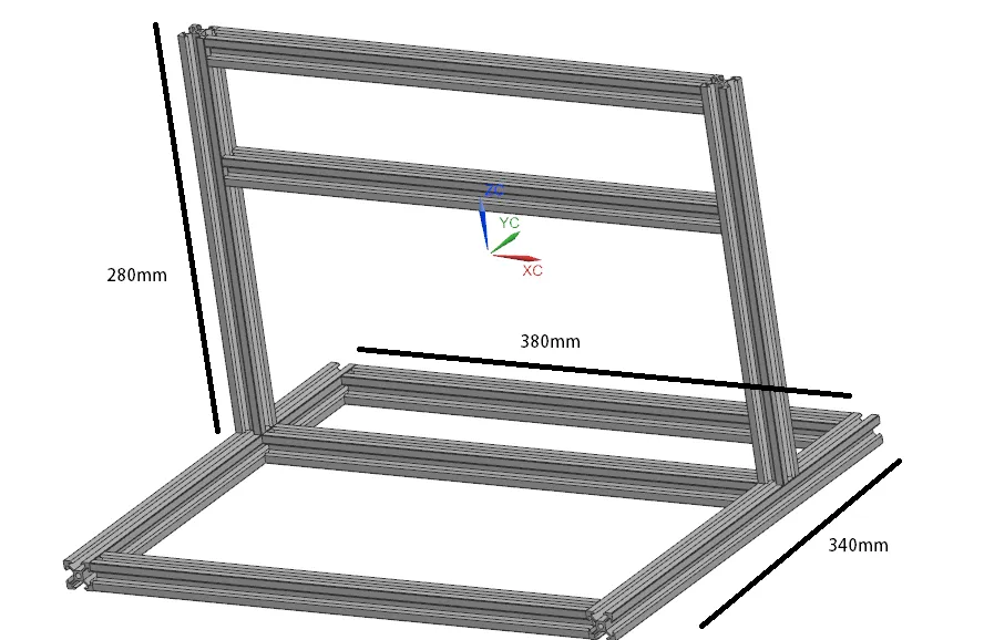
Assemble the Frame in the given picture
Attach bearings to the Y-Axis and fit is inside the frame in the given pictures- If the bearings are tight, use sandpaper
- If the bearings a loose, take tissue paper (as a filler) and surround the hole with it and fit the bearings.
The 380 mm extrusions run across right to left, giving the width of the machine
The 340mm extrusions run along the x-axis
The 280mm extrusion run from bottom to top, giving the height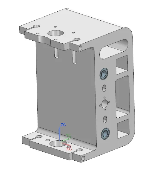
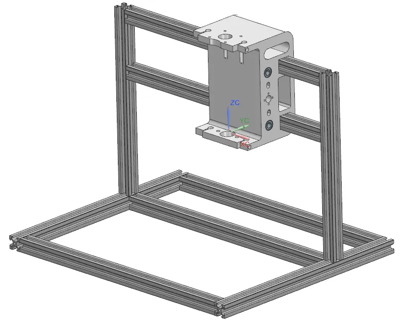
Then attach all the corner bracket pieces with M4 SHCS screw (6mm length) washer and t nuts.
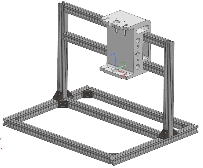
Attach the vertical supports, or the Long L bracket with M5 screws and t nuts
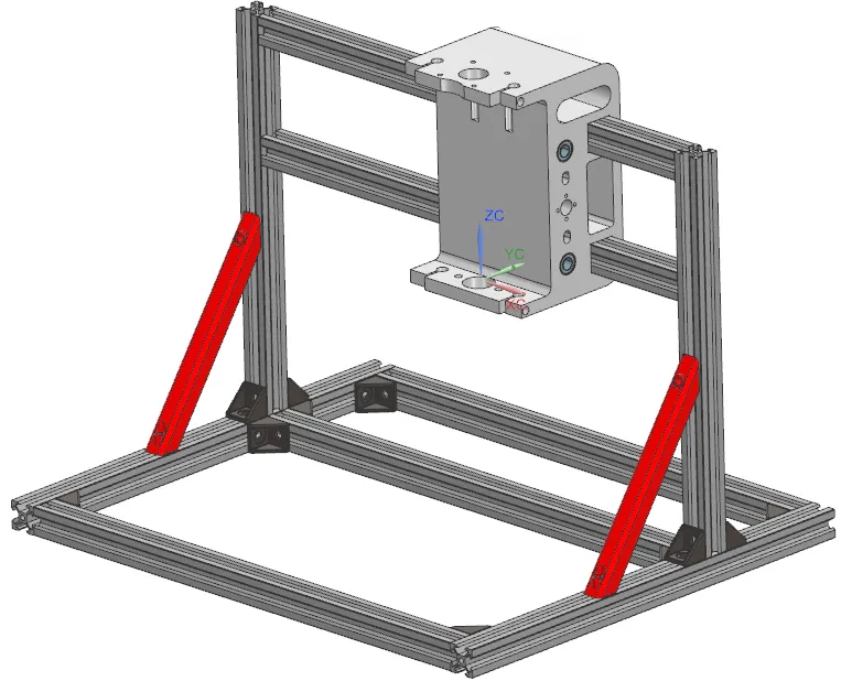
Attach the Side mounts for the y axis.
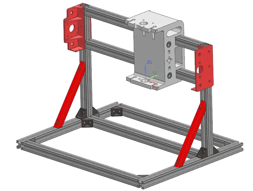
Attach stepper motors with M3 SHCS length 20mm screws with 12mm spacers(3d printable)
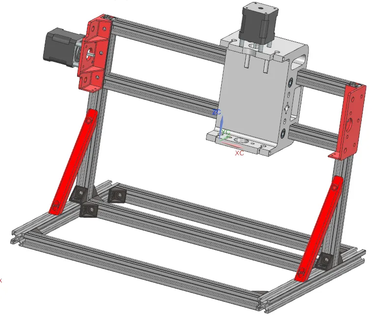
Attach the 8mm lead screw end support bearings
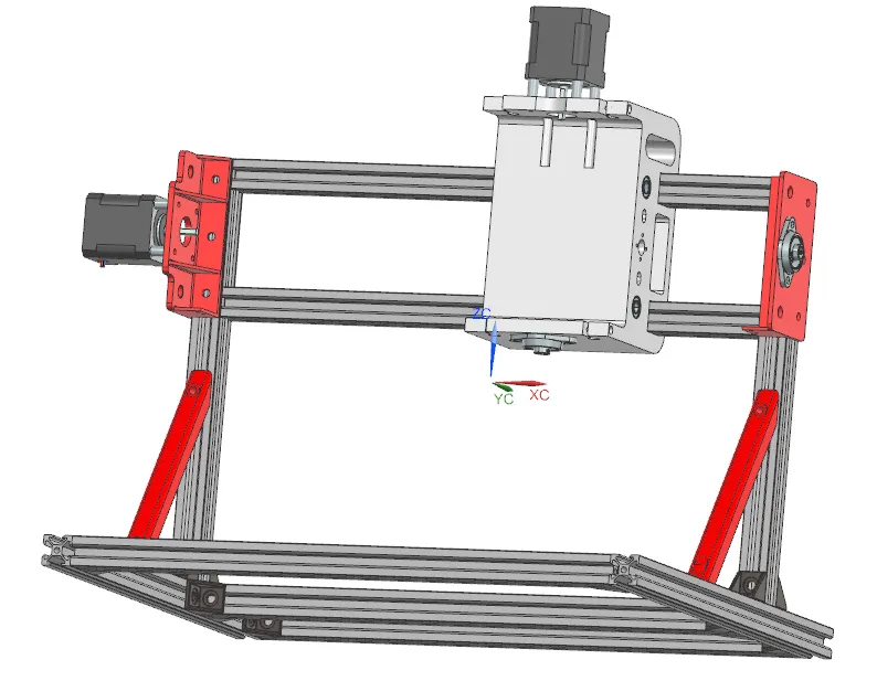
Attach flexible couplers to both the motors
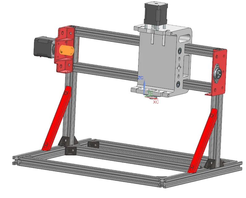
Attach the 2 8mm rods and the lead screw
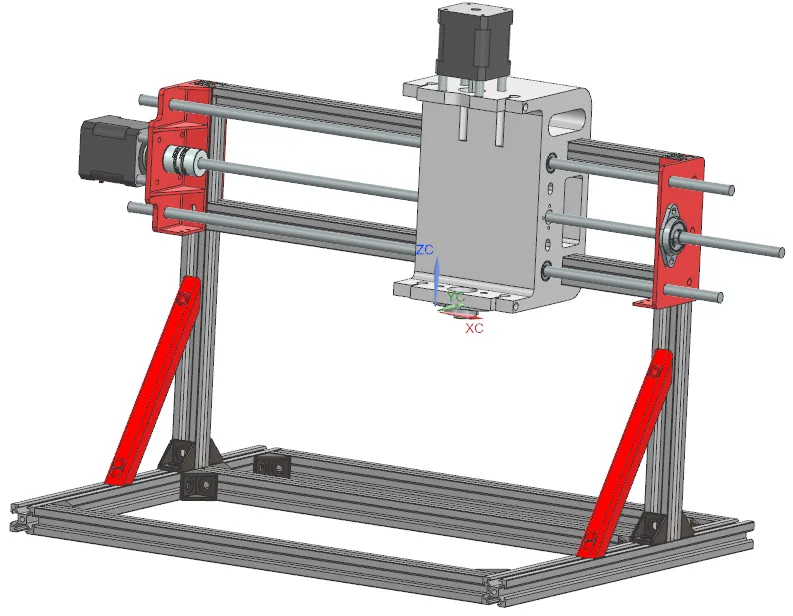
Now, fit bearings on to the z axis assembly
and also attach the T8 nut on it with M3 SHCS screws of length of 6mm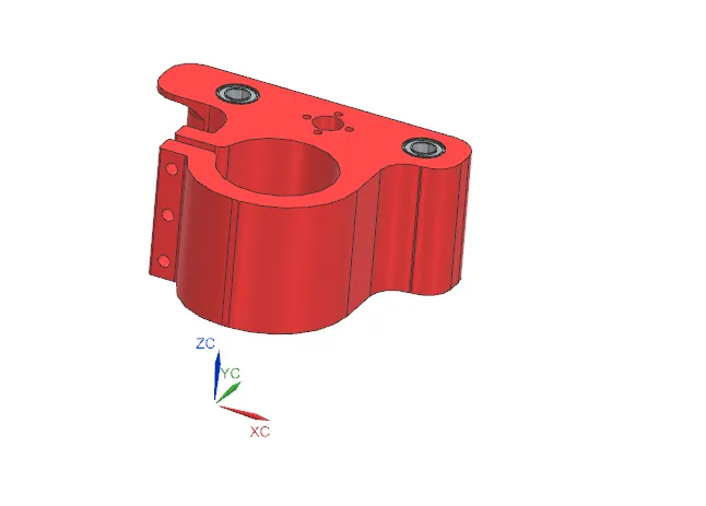
Now, complete the whole Z-axis assembly with lead screws, 8mm rods.
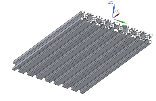
- Now, let's make the bed of the CNC
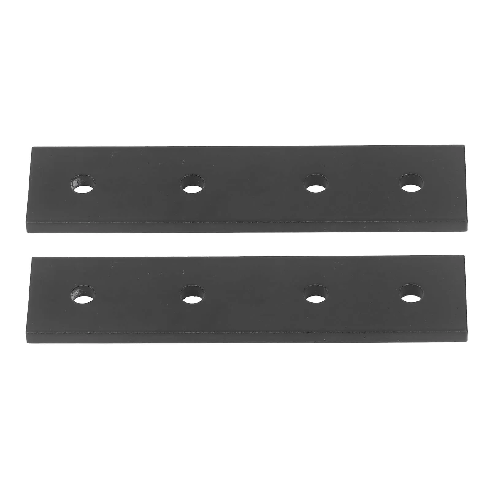
Attach 4 2040 extrusions along their length with the help of long brackets
shown below. 4 of them can be used in conjunction to connect them.
Attach the bearings blocks on the adapter block with Philips round head screws length 6mm, then attach the block onto the bed with M4 SHCS screws of length 6mm
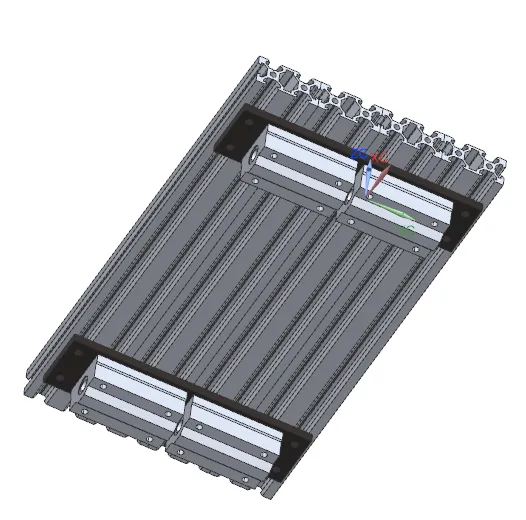
Attach the T8 Nut coupling and the X-axis limit switches with the help of M4 SHCS screws, length 6mm
Also attach the T8 nut onto the coupling with M3 SHCS screws of length 6mm
Now attach the stepper motor to the adapter bracket with M3 SHCS screws of length 6mm
Then attach the block to the frame with M5 SHCS screws of length 14mm
also attach the Flexible coupling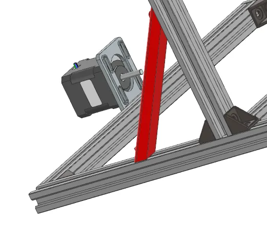
Now attach the linear motion shaft support to the frame, Make sure they are equally spaced from the stepper motor and not so far away from it.
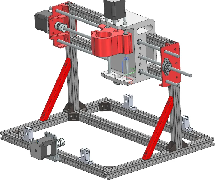
Now attach the supporting bearing block(KP08( of the 8 mm lead screw on the other side of the stepper motor with M4 SHCS Screws of length 8mm. with 4mm 3d printed spacers between the frame and the block
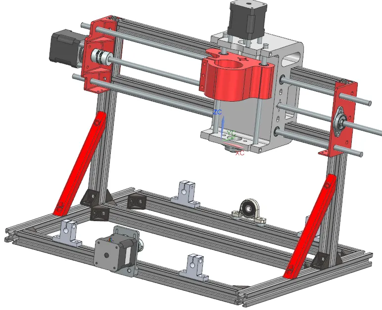
Now attach the 8mm rods, the lead screw, the bed on to the rest of the machine in a systematic manner
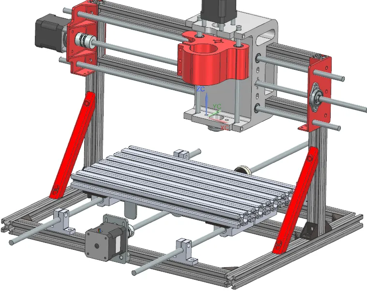
Then attach the adapter for the X-axis limit switches, making sure they align with the part that presses on them on the bed.
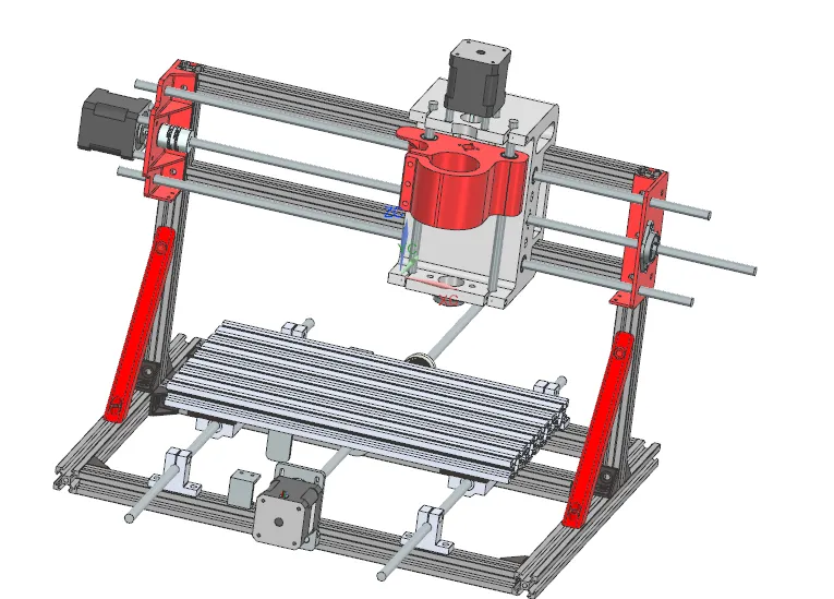
Now attach the limit switches on the y-axis, x-axis, and z-axis.
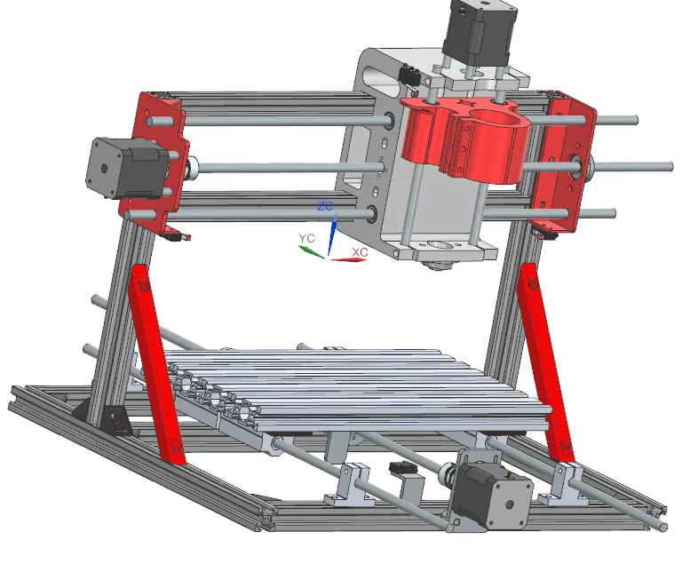
- That's it!
Make sure you oil up the smooth rods, the lead screws, the bearings and especially the extrusions the y-axis is riding on!
License



Comment & Rating (27)