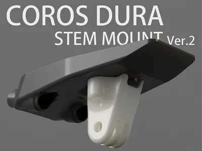
High-speed DURA Stem Mount (27mm) Cycle Computer Mount V2


Print Profile(1)

Description
A handlebar mount designed for the COROS DURA cycling computer.
* Version 2 now available, featuring an added mount for downward-facing lights/cameras!
First, measure the distance between the centers of your handlebar clamp bolts. If it's 27mm, this computer mount should be compatible. See the image below.

Print settings recommendations:
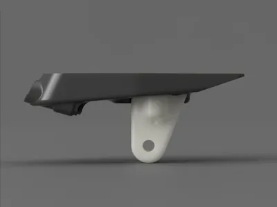
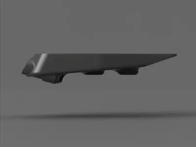
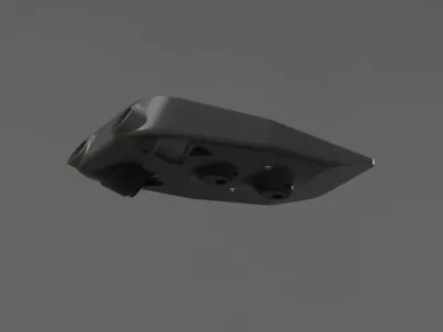
ASA or another weather-resistant material is recommended. The image shows a high-strength PET-CF version.
A layer height of 0.1-0.2mm is suggested, depending on the desired precision.
Use a 0.4mm nozzle and 0.4mm line width. Infill should be 25%-35% based on material strength, with 5 perimeter layers, 5 bottom layers, and 5 top layers.
Assembly components and tools:
① Computer mount replacement base (bolt center distance 21mm. Original mounts are becoming increasingly difficult to source; this version uses a common replacement. The finished product in the image utilizes a 19.9 yuan accessory kit from Maijin)
② Four M3*4 (nut height)*5 (nut outer diameter) heat-set threaded inserts (available at any hardware store; a commonly used component in Voron printer assembly)
③ Two M5*8*30 aluminum alloy bushings (35mm length may be necessary depending on your handlebar, adding 5mm to the length of the securing bolt)
④ Two M3*12 countersunk screws
⑤ Two M5*45 handlebar bolts (stainless steel or TC4 titanium alloy recommended)
⑥ DP460 resin adhesive (likely overkill for the computer mount; use any adhesive you deem sufficiently strong)
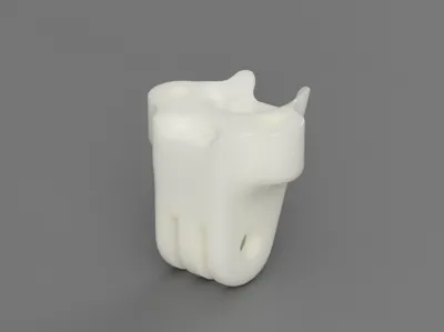
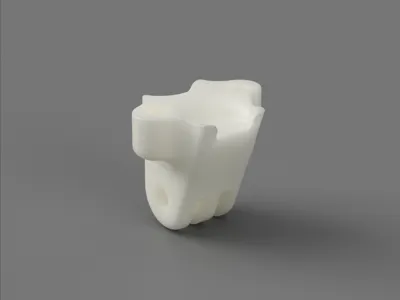
⑦ Printed part
Assembly:
① Remove all supports and clean up any print artifacts
② Apply a thin layer of adhesive to the channels using a cotton swab, as indicated in red in the image

③ Insert the M5 bushing into the channel until its head is flush with the front of the printed part. Wipe away any excess adhesive

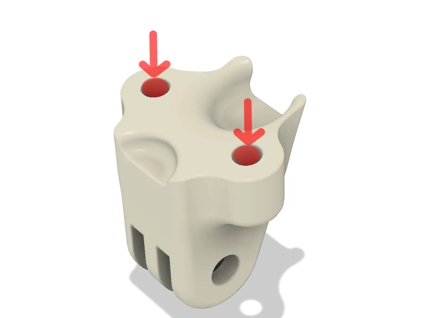
④ Using a soldering iron, insert the heat-set threaded insert into the printed part as shown (ensure the insert's end is flush or slightly recessed)

⑤ Using a soldering iron, insert the heat-set threaded insert into the printed part as shown (note the angle for smooth screw insertion during later light mount installation)
⑥ Secure the computer mount to the handlebar using M5 screws (apply the correct torque; typically below 5.5N. Avoid excessive force to prevent damage!)
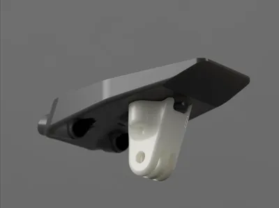
⑦ Secure the light mount using M3*12 countersunk screws, as shown below

⑧ Secure the computer mount replacement base using the provided M3 countersunk screws (ensure screw length does not exceed the printed part). If the print is accurate, the base should be flush with the recessed portion of the printed part after installation.
⑨ Installation complete! Attach your computer and enjoy the ride! It's advisable to use the included strap for added security (observe traffic laws and prioritize safety).
Comment & Rating (1)