Simson GPS Speedometer Case


Print Profile(1)

Description
🛠️ Speedometer Wiring Instructions
1. Ground (Black)
The black ground wire from the speedometer connector is extended with an additional cable. This extension splits into:
- a cable to the button
- another cable to the ground point on the frame
2. Blue Cable
The blue cable from the speedometer connector is directly connected to the button.
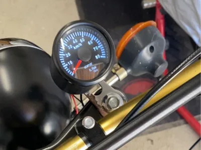
👉 Note: See images for the exact cable routing.
3. Plus (Red & Yellow)
- The red and yellow cables from the speedometer connector are soldered together to obtain a common ignition plus.
- A crimp connector is attached to this cable, which leads to the ignition switch (terminal 15/51) of the moped.
- The original plus cable is then reconnected to the crimp connector.
👉 Note: Observe the illustrated representation.
⚠️ Important:
Before crimping the cables, first run all cables through the speedometer! Or use connectors. The GPS antenna can also be connected beforehand.
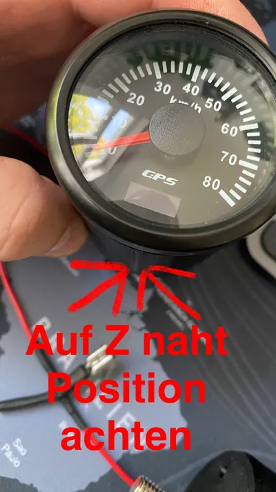
🔧 Assembly Instructions
- When inserting the speedometer into the housing, ensure that the rubber seal sits cleanly and is correctly covered.
- When 3D printing the housing, the Z-seam position should be considered.
- The button fits very tightly – if necessary, press down with something pointed and secure it with a hot glue gun.
- The housing fits tightly onto the speedometer – carefully check all connections before installation before the speedometer is finally pushed in.
📏 Recommended Cable Lengths
Cable Type Length (approx.)
- Red (Plus): approx. 910 mm
- Black (Ground): approx. 300 mm
- Button Wiring: approx. 80 mm
💡 Tip: It is better to make the cables a little longer – cables that are too short can be difficult to correct later.
📋 Required Components
- 1× Mini push button (6×6×9 mm)
- 1× M8 screw (SW13)
- 1× Ring eyelet for ground connection
- 1× Crimp connector (male + female)
- 2× Cable extensions (for plus and ground)
Boost Me (for free)
I would be happy if you leave a rating or a boost, have fun with the part. :)
License
You shall not share, sub-license, sell, rent, host, transfer, or distribute in any way the digital or 3D printed versions of this object, nor any other derivative work of this object in its digital or physical format (including - but not limited to - remixes of this object, and hosting on other digital platforms). The objects may not be used without permission in any way whatsoever in which you charge money, or collect fees.
Comment & Rating (5)