Over-Engineered Y-Splitter


Print Profile(7)


Description
Updates
Version 2.1 (09/27/23)
- Added lead-ins to the filament entry cavity
- Changed PTFE stop ledge angle at filament exit end
- Added note about countersinking PTFE that enters the printer
- Updated printing profiles
- Added additional sources for the release rings so they can be purchased outside of the US
Version 2
- Added through hole for an M3x20mm mounting screw. Printed with a 0.4mm nozzle at 0.10mm layer height
- Added printable locking clip STL file to eliminate backlash in fitting/PTFE tube when pulled on
- Print with single inlet side on the build plate. Add a 10mm brim to stabilize the print
Version 1
Background
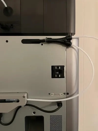
This allows you to run material from the AMS or external spool without having to disconnect the PTFE tubing.
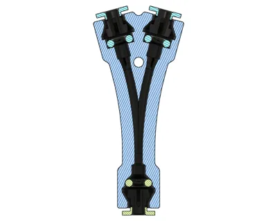
This uses push to connect fittings as you would see in a typical PTFE connector.
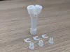
Release Rings: QTY: 3 of PC4-UM2
I do NOT recommend the printed release rings as they are too fragile and do not securely hold the PTFE tube into place.
Amazon (https://www.amazon.com/dp/B0B282NZVW?ref=ppx_yo2ov_dt_b_product_details&th=1 )
AliExpress (https://www.aliexpress.us/item/3256804490680277.html?gatewayAdapt=glo2usa4itemAdapt)
McMaster (https://www.mcmaster.com/5472K101/)
Installation
Push the retaining ring into each end. After you insert the PTFE tubing until it bottoms out, pull back so the release ring has a gap between it and the printed surface. Insert the locking clip into this gap and then push the PTFE back in so it seats. This removes any backlash so the end of the PTFE tube remains firmly in contact with the bottom of the bore.
While not always required, I found it helps to countersink the PTFE tube entering the printer as it provides a lead-in to prevent snags.
You also need to ensure the printer buffer operates as intended. The PTFE tube exiting the buffer needs to clear the AMS clip going into the back of the printer. This prevents any unwanted resistance to the buffer and let‘s it operate as intended. If not, you can see what looks to be like a partial clog or even failure to retract filament.
Comment & Rating (482)