
66160 Lithium Titanium Oxide Battery Pack Frame
Print Profile(1)
Bill of Materials
- 1/4"-20 threaded rod - 19cm long x 2: For axial compression
- 1/4"-20 threaded rod - 16cm long x 2: For vertical hold down
- 1/4"-20 nylock nuts x 6:
- 1/4"-20 wing nuts x 2:
- 1/4"-20 washers x 2:
Description
Boost Me (for free)
Please support the design and free publication of functional parts which return autonomy and control to the consumer. Every boost is greatly appreciated as it supports further time investment in creating these models!
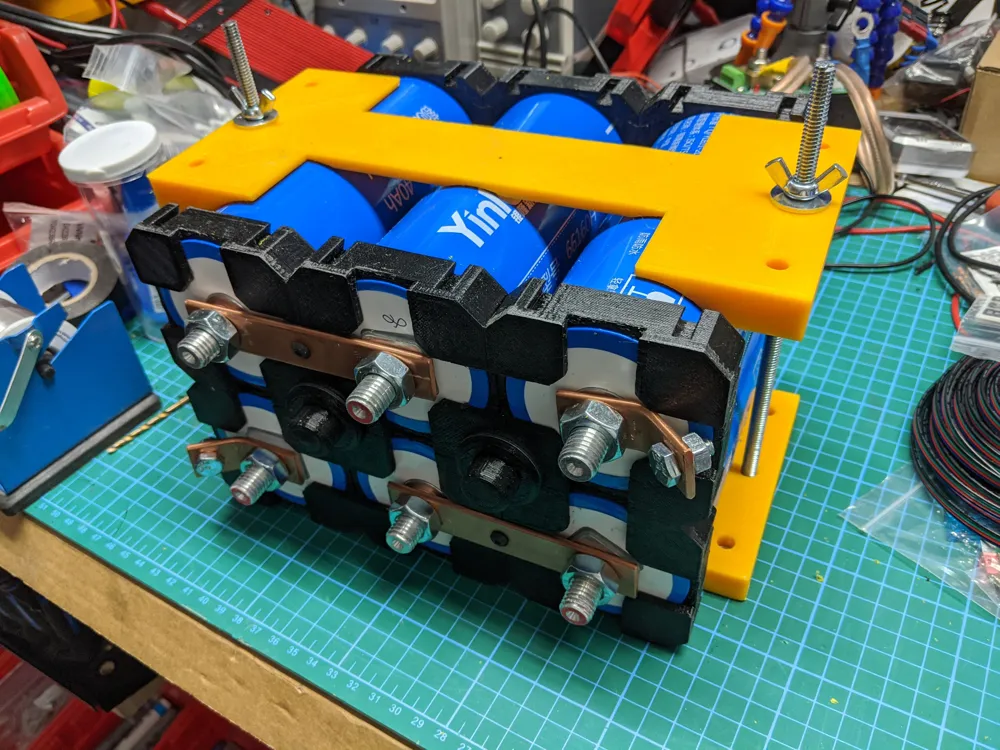
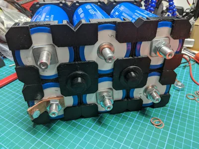
- This model is intended to be a mounting mechanism for 40Ah 66160 sized lithium titanium oxide (LTO) battery cells (made by a company called Yinlong).
- Safety warning: LTO battery cells are capable of incredibly high current output if short circuited which can cause burns, or ignite fires due to the heat produced by short circuit. LTO cells on their own are relatively safe compared to Li-ion or LiFePO4 cells, but the surrounding objects may still be flammable. Conduct your own risk assessment as you assemble the cells.
- This model does not account for your electrical design, cell balancing, overdischarge/short circuit protection, etc. You must properly design your battery pack. This model only provides a sturdy mechanical assembly for the cells.
Printing
- The print profile has already laid out the parts required to construct a 6s battery pack - 12x endcaps, 28x connector wedges, and 4x fender washer caps.
- If you want to customize your size of pack, simply print the necessary number of parts.
- Connector wedge note: these are slightly tapered wedges - they have been oriented wide-side to the build plate with a brim to assist printing. If you are confident in your build plate adhesion you can disable the brim to save cleanup time.
- Frames should be printed in heat-resistant materials such as ABS, nylon, etc, during high current discharge the cells may get warm. If you intend to use this in automotive applications, it is even more critical to print these in heat-resistant materials. PLA is not safe and PETG is questionable.
- Optional: print the end caps in sets of red/black filament, to minimize the risk of assembly errors and short circuits.
- Optional: print buss bar test pieces to use as non-conductive placeholders for copper bus bars, and use them as a cutting template for your buss bars.
Assembly
- Safety warnings:
- It is highly recommended that you clear your workbench of all unnecessary metal objects, and wrap any wrenches or other tools you want to use in proximity to battery contacts with insulating electrical tape so that the risk of accidental short circuits is reduced when tightening nuts.
- All flammable liquids, solvents, or other objects should be cleared from your work area before starting.
- Frame Assembly
- Lay out the end-caps in the configuration for your pack (if you want a flat pack, lay them side-by side, or in a grid for a rectangular pack).
- For each endcap connection one-at-a-time:
- Add a small amount of superglue/cyanoacrylate glue (CA glue) to the dovetail slot on each side.
- Using a deadblow hammer or rubber mallet, hammer the connecting wedges in (narrow side down) into the dovetail slots to join the end-caps together.
- Continue until you have all connection points completed. Repeat for the second battery frame.
- Prepare Threaded Rods and Sub-assemblies
- General note on threaded rods: Ensure you inspect, and debur/bevel the ends so that the threads are in good condition to accept a nut.
- Axial pack compression:
- For a 3x2 battery pack, you will need 2x ¼"-20 threaded rods 19cm long.
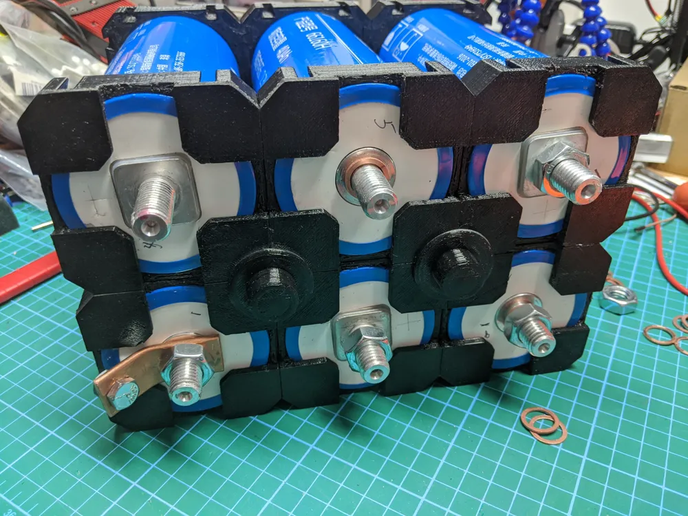
- Using a dead-blow hammer, gently tap in a ¼"-20 nylock nut into each fender washer cap, with the nylon side facing down into the cap. These are designed as an insulator to minimize the risk of shorts during assembly.
- Using pliers or vise grips on the 19cm threaded rods, screw a fender washer cap onto one end of the threaded rod, leaving the other side open. Ensure you thread it far enough so that the nylock nut engages and does not spin freely.
- Vertical pack hold-down:
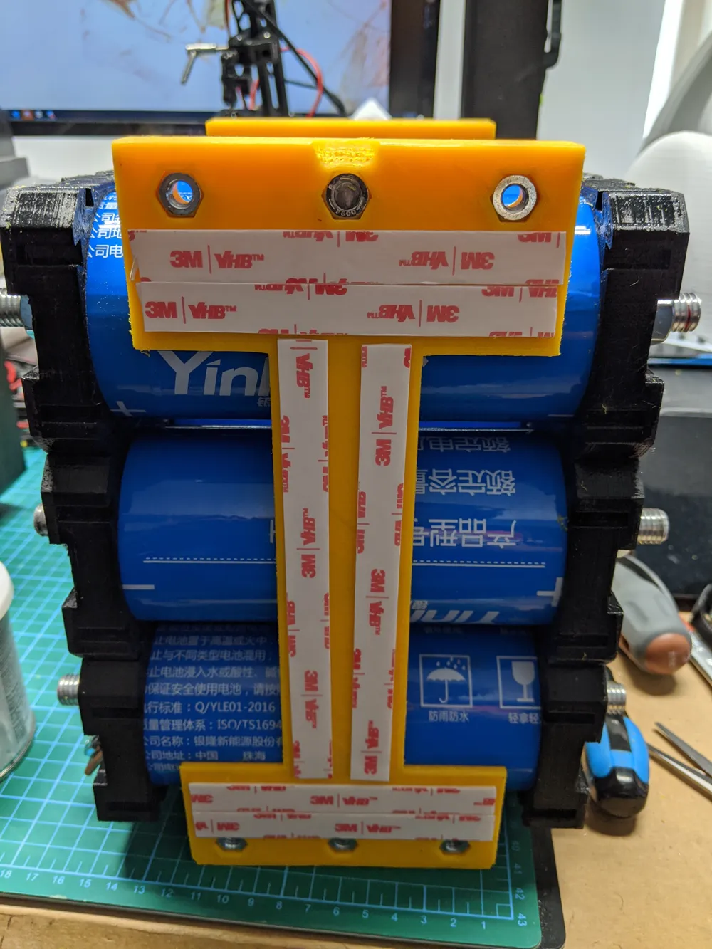
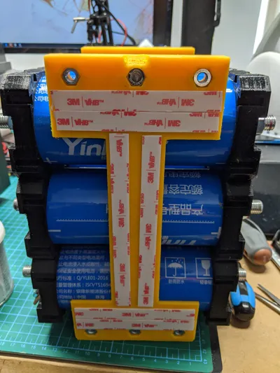
- If you are building a 3x2 battery pack you will need 2x ¼"-20 threaded rods, 16cm long. If you are not building a 3x2 battery pack, you will need to develop your own hold-down solution.
- Using a dead-blow hammer, gently tap ¼"-20 nylock nuts into the lower hold-down with the nylon side facing out.
- Use a pair of pliers or vise grips to install the 2x 16cm ¼"-20 threaded rods into the nylock nuts, ensuring to thread them far enough that the nylon threads engage.
- Optional: instead of only doing 2x threaded rods for hold-down, you can do 4 or even 6 rods, as extra holes have been designed into these parts.
- Optional but highly recommended: install heat-shrink over the threaded rods - without the heat shrink, if you scrape the side of your LTO cells against the threaded rod and cut through the insulating shrink wrap, you risk a short circuit. You will need to measure and trim the heat shrink to length, as there will be some slight axial shrinkage to the tubing.
- Assemble Pack
- Using masking-tape rolls or other non-conductive objects, elevate an assembled battery frame.
- Begin inserting your 66160 cells into the pack, observing the polarity and direction.
- It is best if you have a written sequence and orientation planned out in advance to ensure you have the cells facing the correct direction once you start assembling bus bars.
- Use a permanent marker to label the ends as positive or negative to make your life easier.
- Rotate the batteries so that you can also read the +/- labels, rather than having them face inwards.
- Install the second battery frame - using an insulated or non conductive hammer (ie: deadblow hammer) gently tap the frame down onto the cells, adjusting them so they are aligned if required.
- Rotate the pack so that you have access to both sides with terminals.
- One at a time, insert the 19cm threaded rod with a pre-installed fender washer cap into the hole between cells and feed it through to the opposite side of the pack. Be careful not to scratch or damage the insulating wrapping on cells. Install the opposing fender washer cap and hand tighten until snug. Repeat for the second threaded rod assembly.
- Warning: Begin sequentially mounting bus bars onto your pack - ensure you are not creating a short circuit!
- You can use printed buss bar test pieces to ‘dry run’ your assembly and ensure you are creating a 6-series pack, rather than risk accidentally creating a short circuit.
- One way to confirm you are not creating a short circuit, is by measuring the voltage between the 2 mounting studs prior to adding the bus bar - there should be no voltage as the pack is ‘open circuit’. If you read a voltage, you are about to create a short.
Boost Me (for free)
Please support design and free publication of functional parts which return autonomy and control to the consumer. Every boost is greatly appreciated as it supports further time investment in creating these models!
License

You shall not share, sub-license, sell, rent, host, transfer, or distribute in any way the digital or 3D printed versions of this object, nor any other derivative work of this object in its digital or physical format (including - but not limited to - remixes of this object, and hosting on other digital platforms). The objects may not be used without permission in any way whatsoever in which you charge money, or collect fees.


Comment & Rating (1)