
10 Yuan DIY High-Power UV Curing Lamp
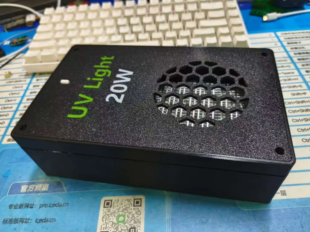
Print Profile(1)

Description
The second installment of the 10 Yuan DIY series, following the well-received 10 Yuan DIY 240W Desktop Charger from lir001 on MakerWorld: Free 3D Model Download, continues the trend~
A high-power 10 Yuan DIY ultraviolet curing lamp, utilizing a 20W UV board, powered by Type-C PD 20V, with a button to switch between three UV irradiation power levels.
Widely applicable for post-curing of resin prints, PCB solder mask curing, UV adhesive curing, and localized sterilization.
The UV irradiation volume is 100mm*180mm*40mm, employing a non-exposed design to effectively prevent UV light leakage.
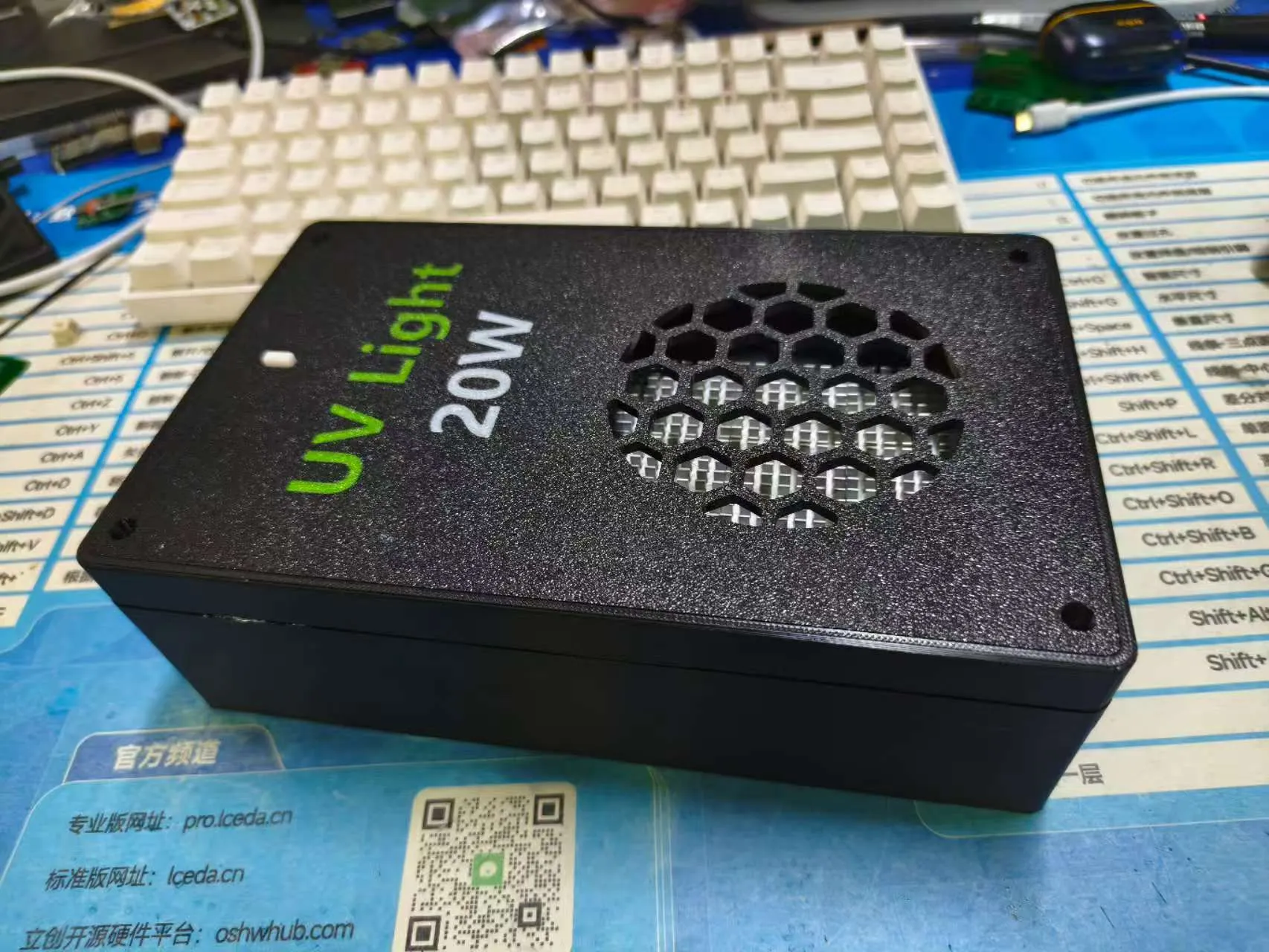
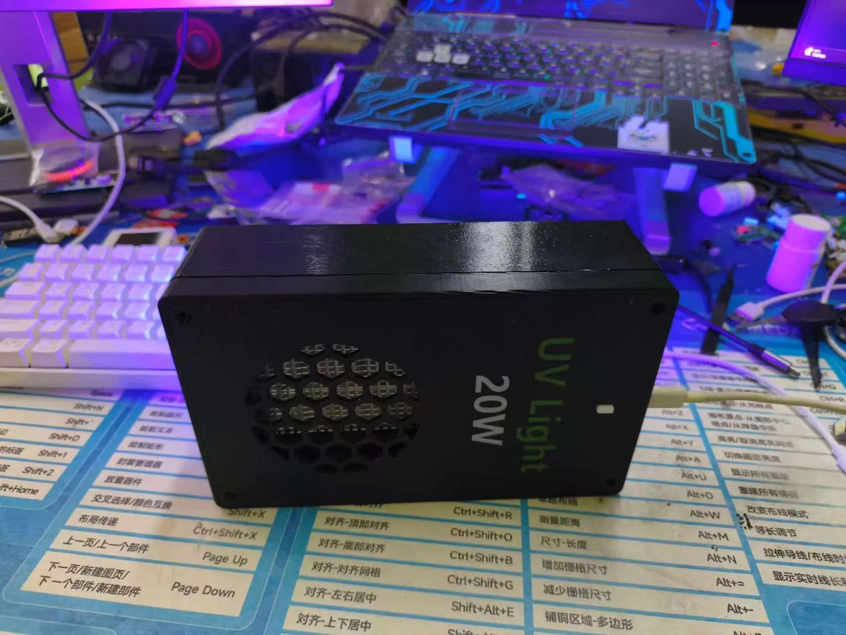
**This project involves PCB fabrication, soldering, firmware burning, and assembly. While it involves multiple components, they are all straightforward.**
Button Functionality:
Short Press- 0%-33%-67%-100% cyclical UV brightness switching
Long press 2s and brightness > 0% to turn off UV
Indicator Light Functionality:
UV brightness = 0: Green light = Type-C POWERGOOD, Yellow light = Type-C NO POWERGOOD (fast charging negotiation failure, adapter lacks requested voltage level, no fast charging)
UV brightness > 0: Alternating flash every 500ms
Required Materials:
M2.6*6 self-tapping screws
M3*30 countersunk self-tapping screws
Heatsink + thermal paste (optional)
PCBA*1
UV board*1
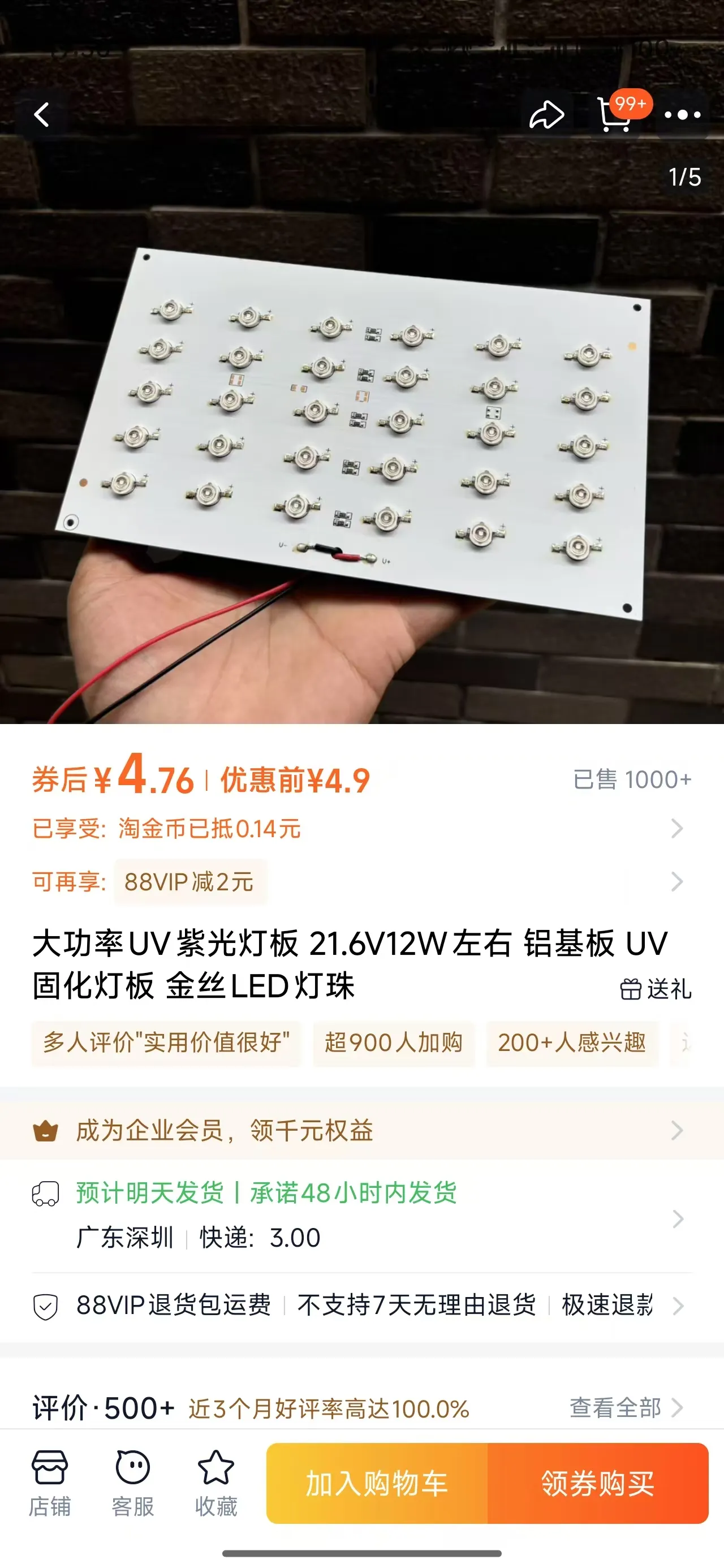
Batch cost less than 10 Yuan
Potentially Necessary Tools:
Hot air gun & soldering station
Burning a blank CH32V003 chip requires a WCH-LINK, or one can be fabricated and soldered for under 10 Yuan
Hardware Section:
Published on the open-source platform 10 Yuan DIY High-Power UV Curing Lamp - Open Hardware Platform, divided into basic and pro versions; the basic version features a 12V decoy and a 10W power limit, lacking dual-color LEDs. The program uses the pro version.
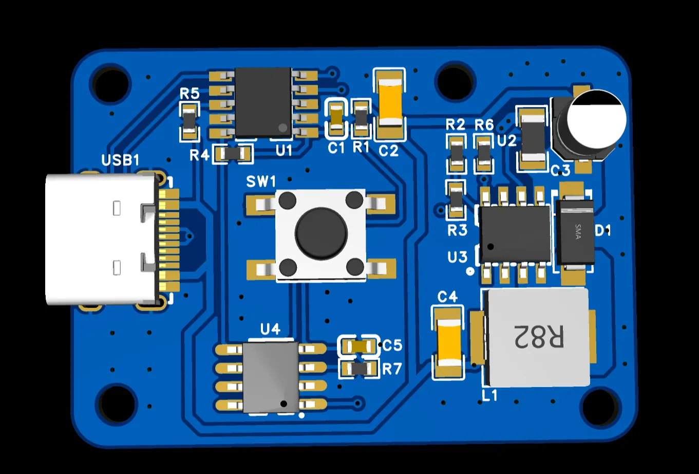
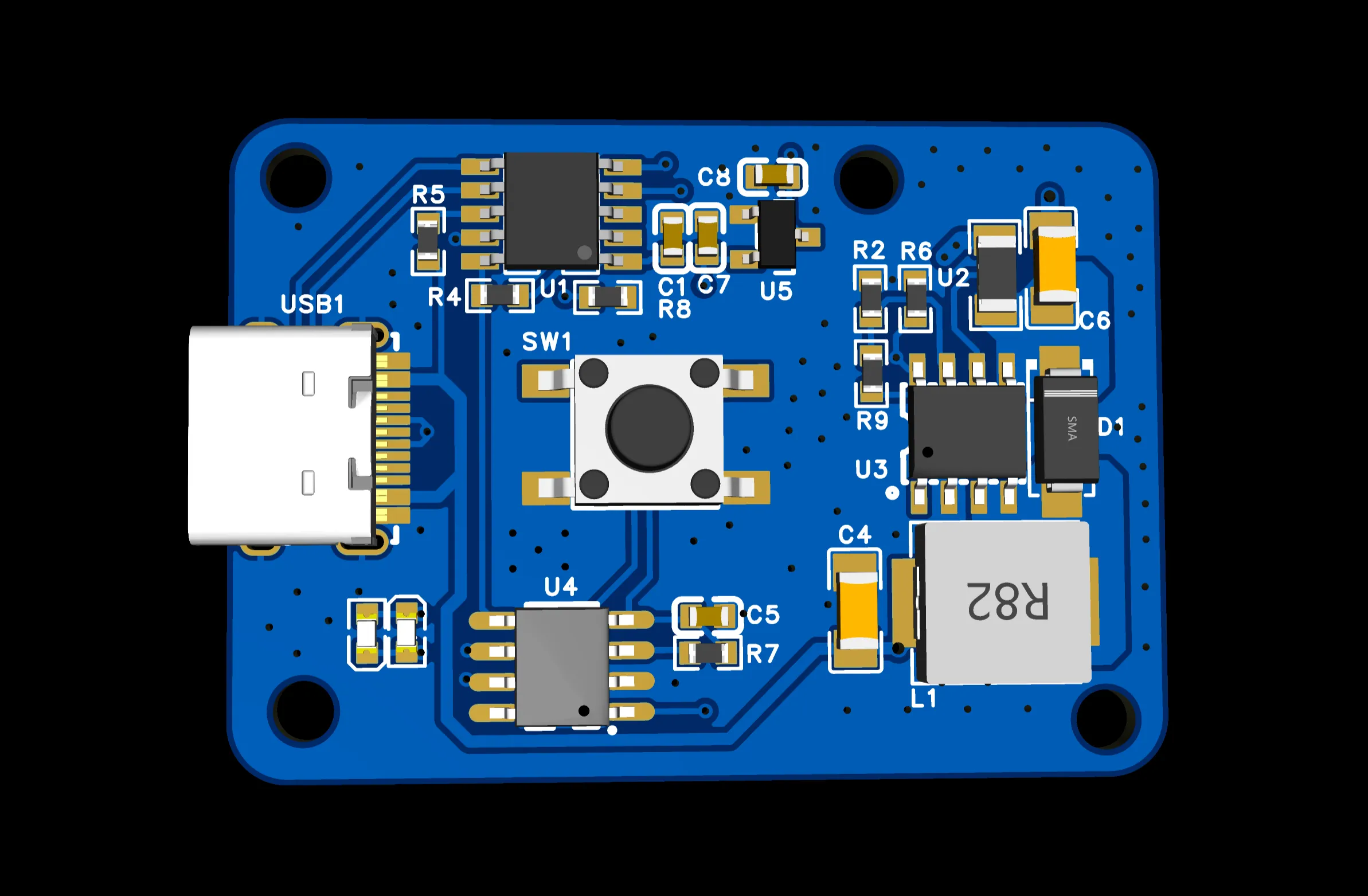
Utilizing the WCH suite, the CH224K decoys the 20V PD level, the MCU uses the CH32V003, and the LED constant current driver uses the flicker-free LGS63042. The combined cost of the three primary ICs is less than 1.5 Yuan.
Software Section:
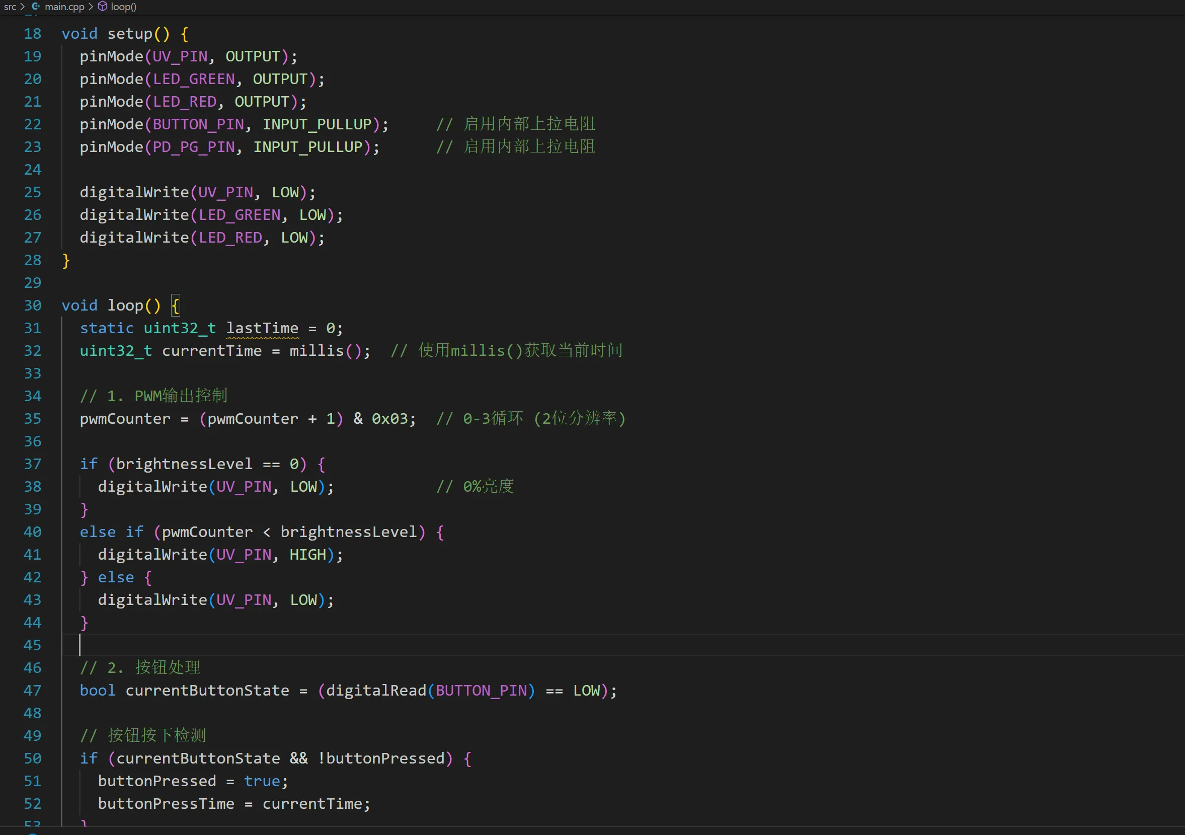
For rapid development, the PIO IDE and Arduino Platform are used. Due to the lack of direct PWM implementation and to avoid rewriting TIM in Arduino, a state machine is employed in the main loop to achieve a software 2-bit PWM, button debouncing for short and long presses, and LED flashing + PG control.
The SWPWM's measured output reaches 110k.
Using WCH-LINK for burning, the programming signal line is the sole test point on the back of the PCBA.
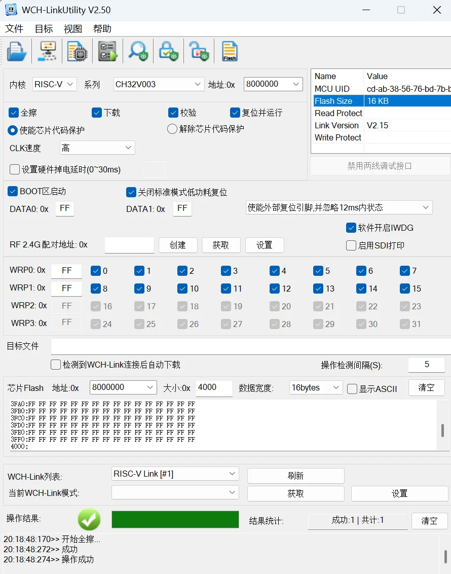
Alternatively, PIO can be used for direct burning (requiring installation of the development environment). Both code and firmware will be open-sourced as needed~
Mechanical Section:
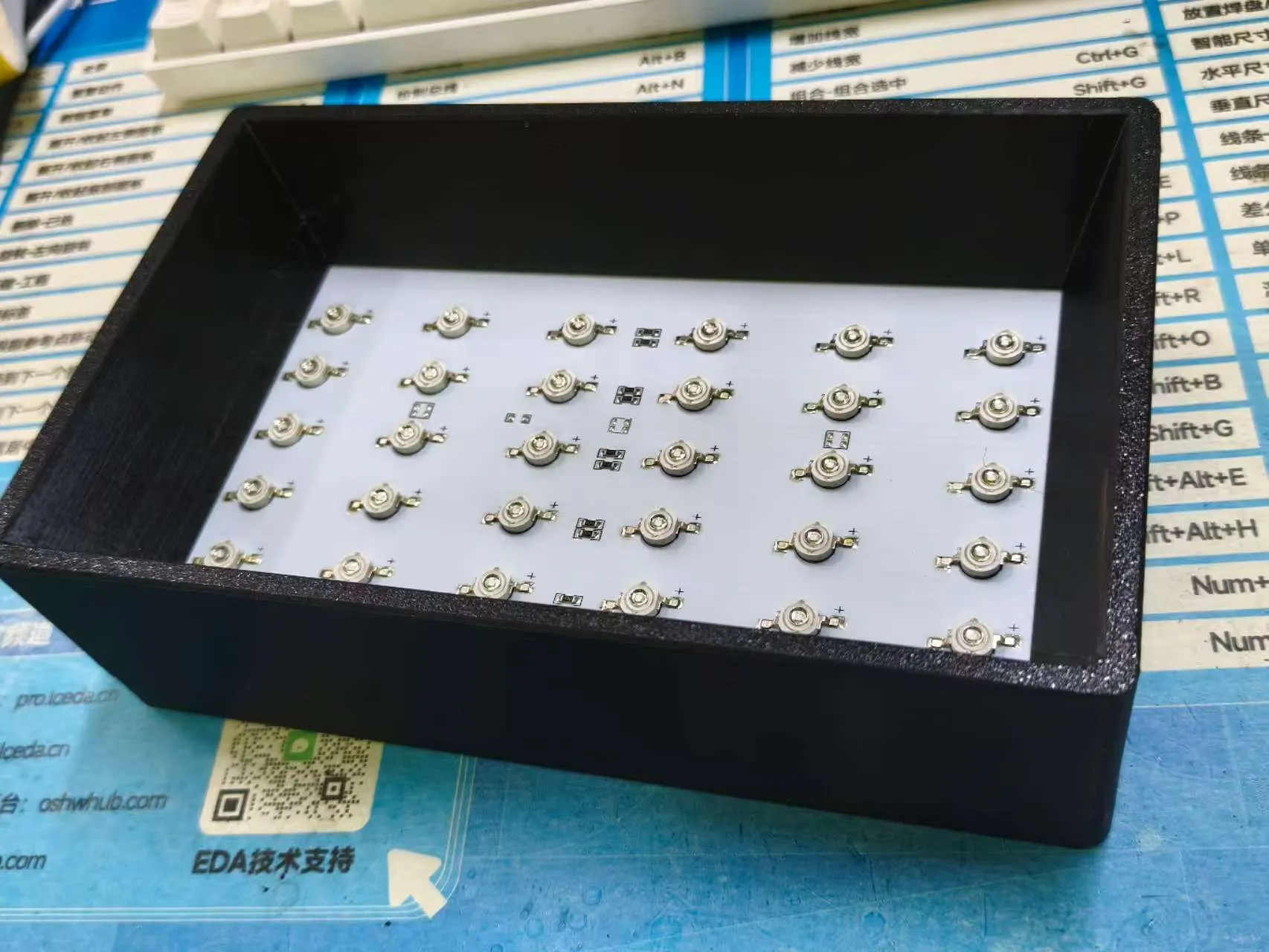
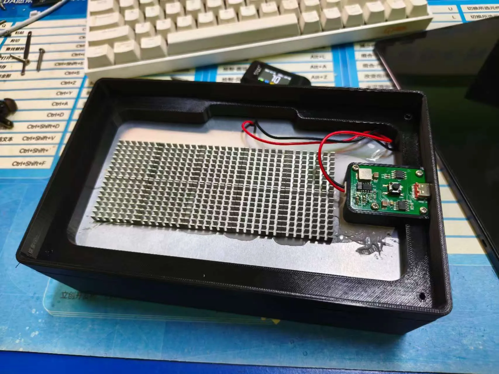
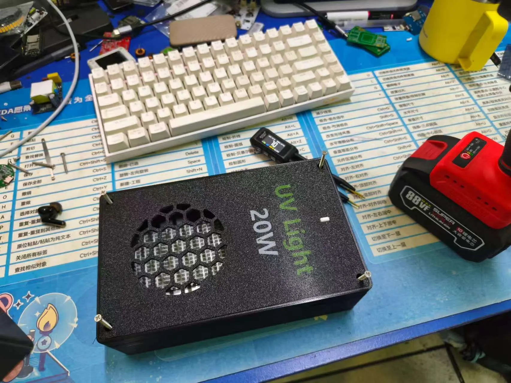
Print all parts; the top cover utilizes embedded text, requiring the AMS. Install as shown in the image sequence below.
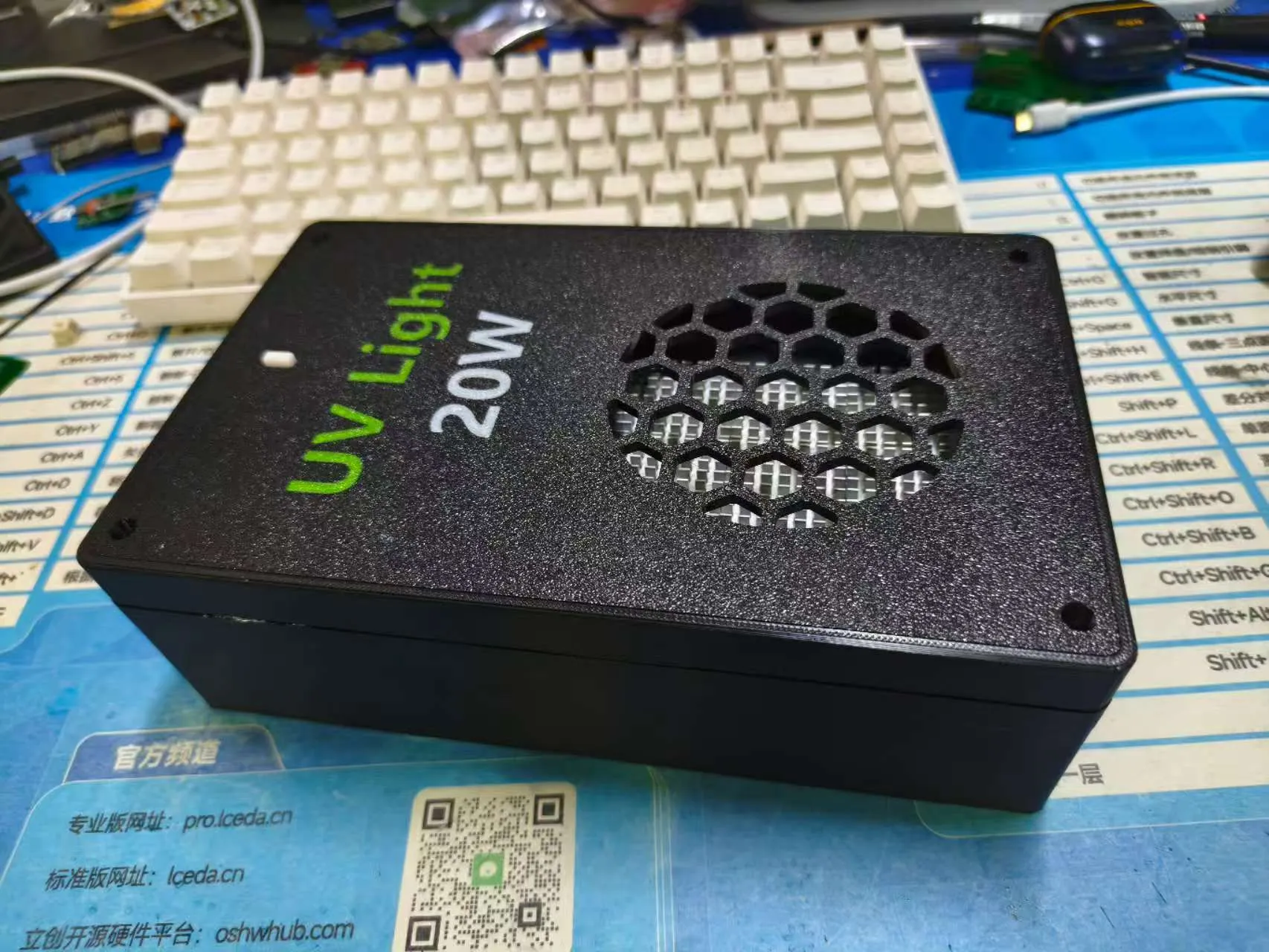
Appendix: Power Test at Various Levels
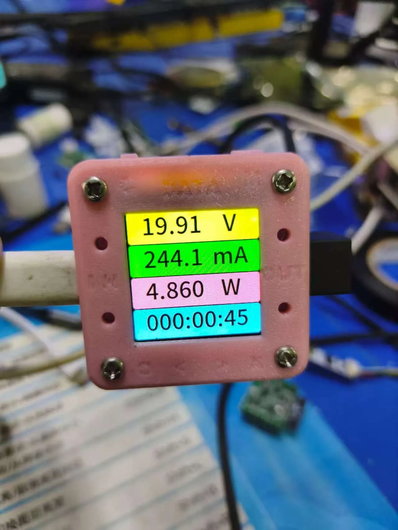
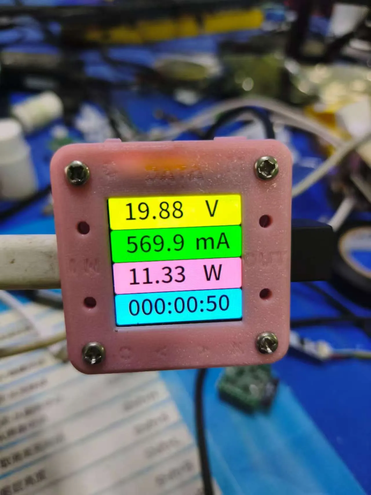
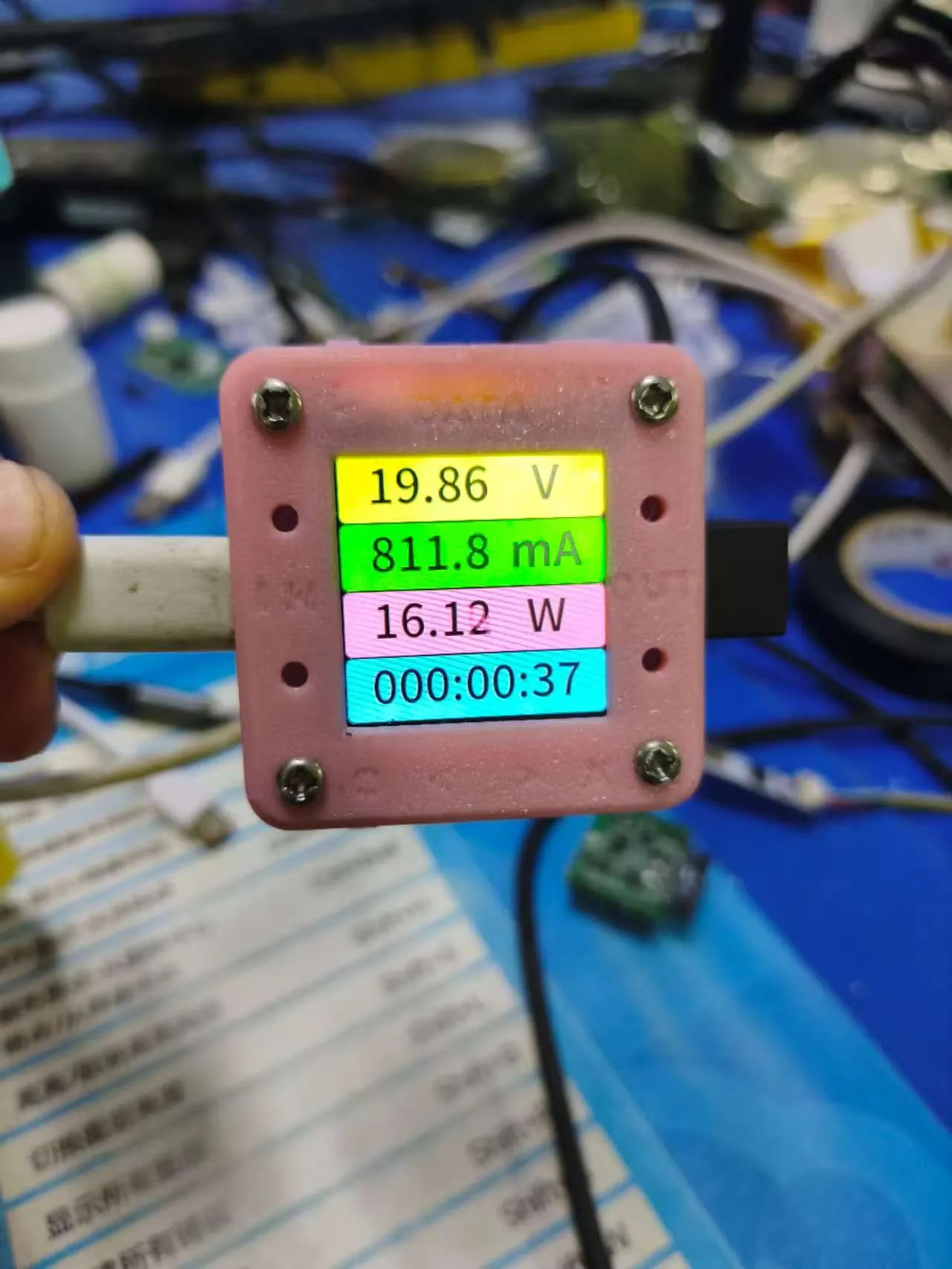
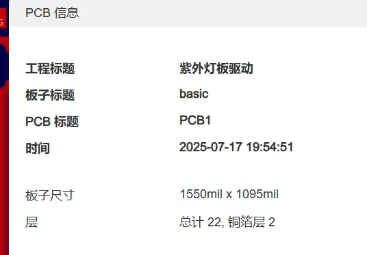
Attachment Description 1: Gerber_PCB1_2025-07-17.zip Fabrication files, information shown below
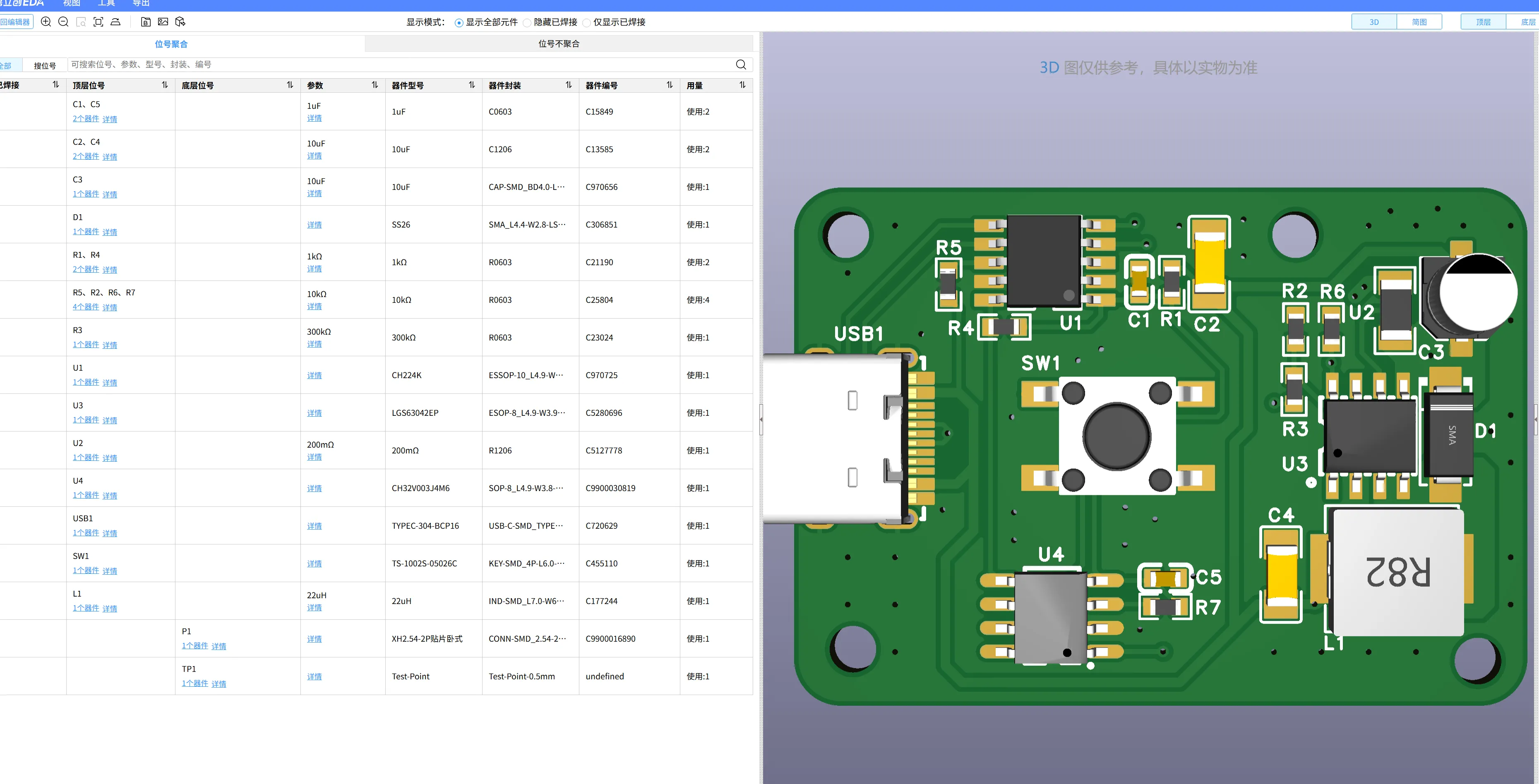
Attachment Description 2: InteractiveBOM_PCB1_2025-7-17 Soldering aid + BOM, open in a browser after extraction
Attachment Description 3: firmware.zip Pro firmware, use WCH-LINK for burning
Documentation (3)
License

You shall not share, sub-license, sell, rent, host, transfer, or distribute in any way the digital or 3D printed versions of this object, nor any other derivative work of this object in its digital or physical format (including - but not limited to - remixes of this object, and hosting on other digital platforms). The objects may not be used without permission in any way whatsoever in which you charge money, or collect fees.


Comment & Rating (0)