
Airbus A320 Speedbrake Mechanism
Print Profile(1)

Description
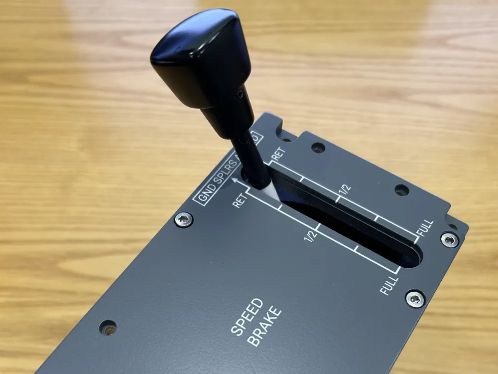
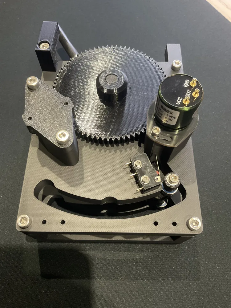
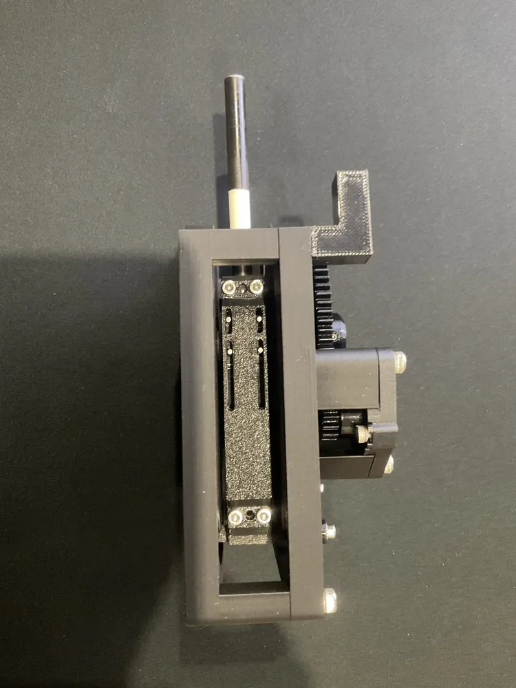
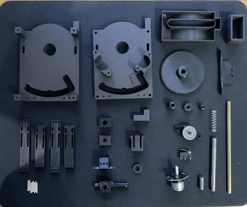
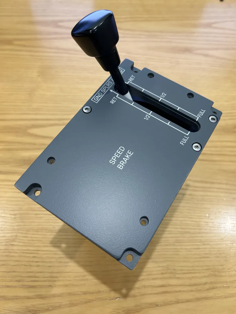
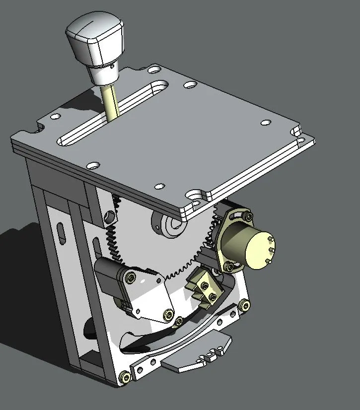
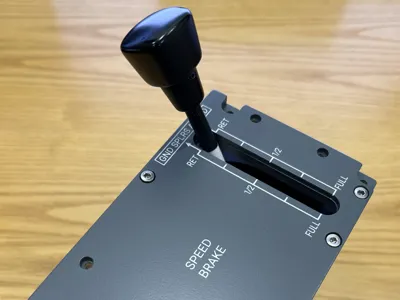
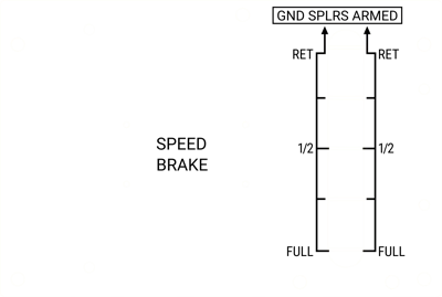
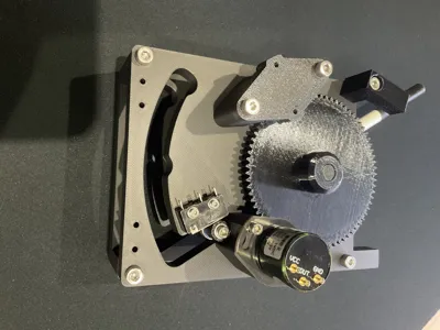
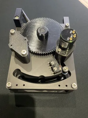
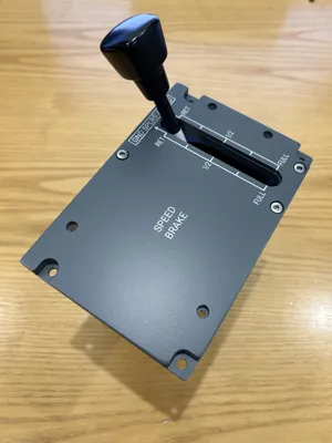
Design to recreate the full functionality of the Airbus A320 Speedbrake. A dimensionally accurate model including a latched pull-up to arm, a locked neutral position, (requiring a downward press to enable manual deployment) and a detent at the half deployed position.
The design objective was to create a realistic feel, with a smooth, solid and weighty action. The design therefore includes steel and brass shafts plus an optional Bansbach C2 rotary damper. Having operated the real lever in a A320Neo cockpit, this design feels very close to the real thing.
Design uses a rotary hall angle sensor for reliability in place of a standard potentiometer. The design could be simpler and use less parts, but it is optimised to feel solid on the basis you only build one :-)
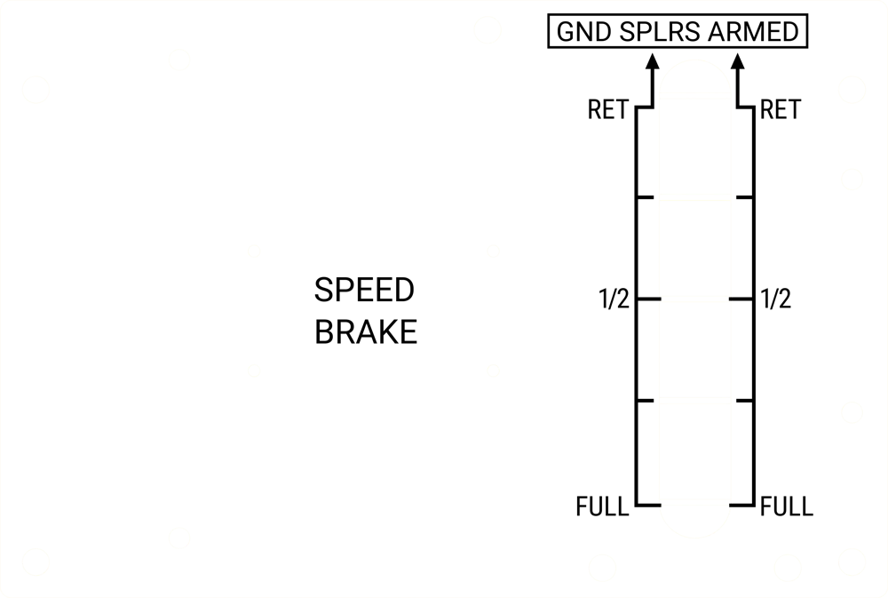
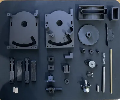
Side Frames, Knob, Slot Light Box and LED Light box can be printed in PLA. For optimal backlighting, panels are best cut from Acrylic, but can be 3D printed. Top layer white, middle and bottom layers clear. Text and line graphic for engraving is included. All other parts, including Gears, Notch and Pivot parts should be printed in PETG, 100% infill for strength, particularly the parts with grub screws. I printed the pivot parts in PETG CF to reduce flex, but this is not essential. It is essential to print the sprung notch part in PETG for its flexibility. Several components are printed in several parts and then glued to optimise layer alignment for strength and create smooth movement that is not against layer lines, plus to allow printing without supports. The only part requiring support during printing is the Slot Light Box, where it was unavoidable.
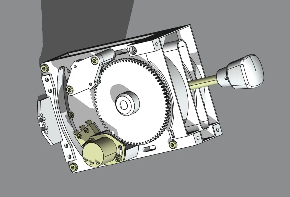
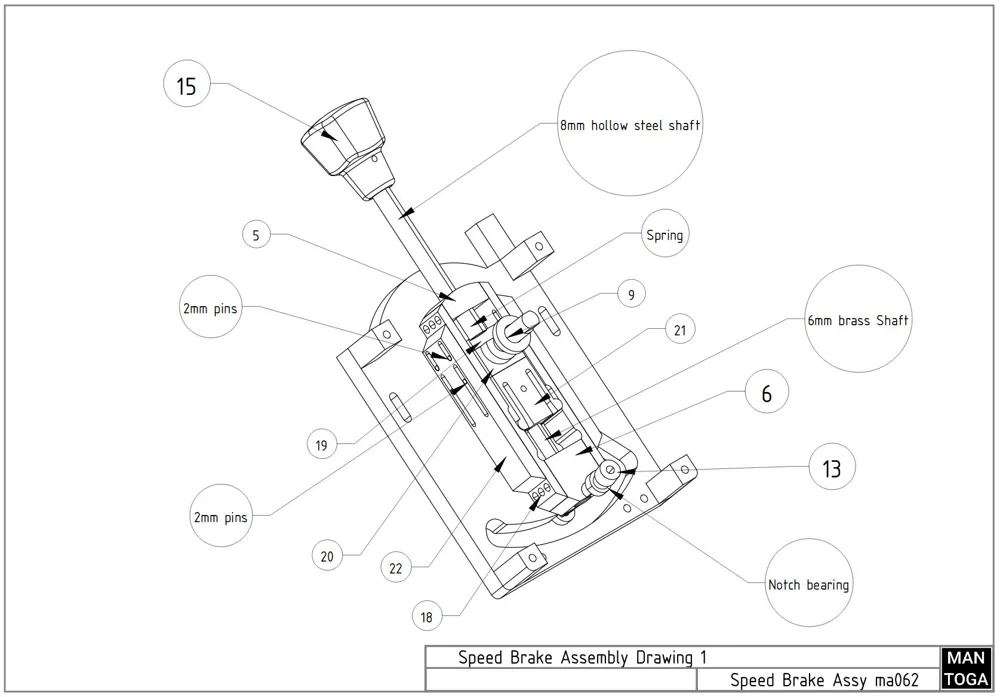
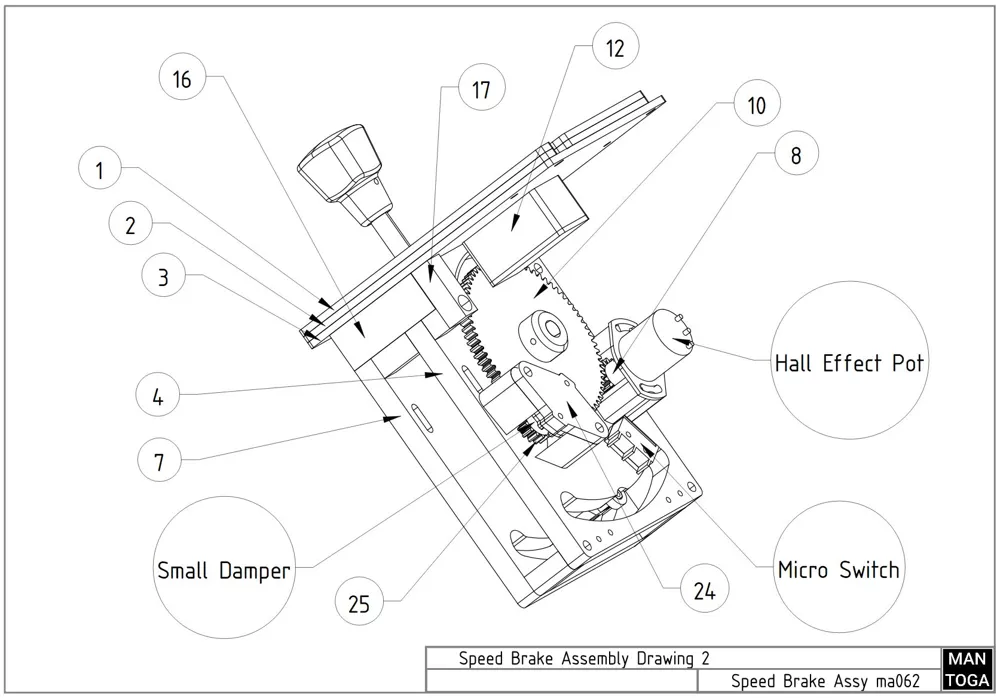
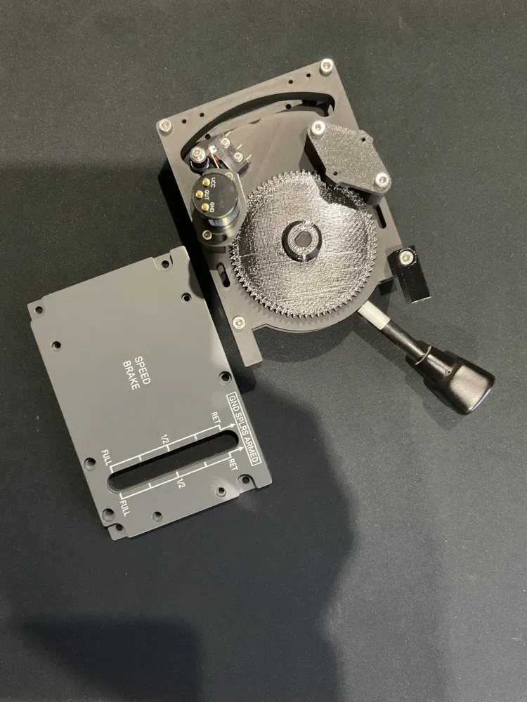
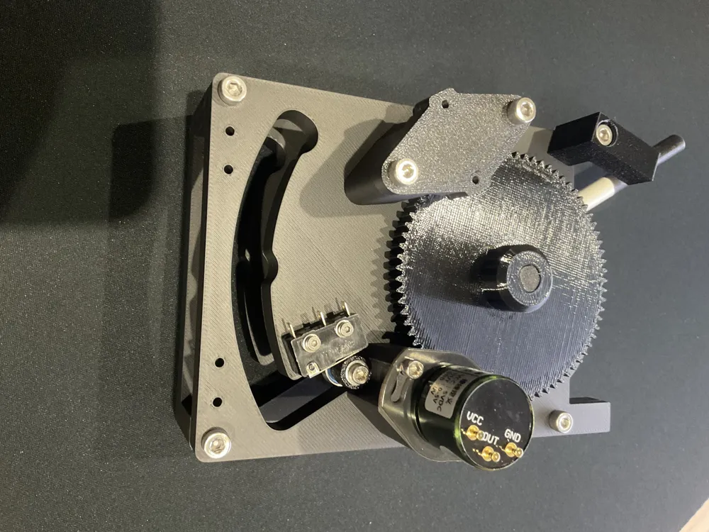
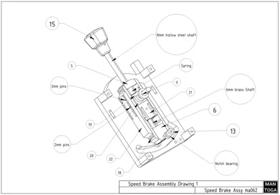
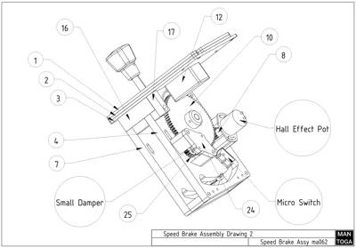
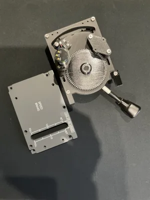
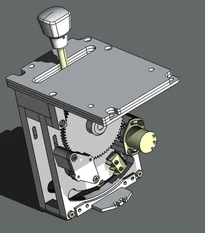
Assembly using screws and CA glue is easier than it sounds and not too complicated. Use CAD images, photos and Assembly Drawings as guides. All printed part files are numbered for reference.
.SVG file for engaving is available for download in .ZIP
Order of assembly is as follows:
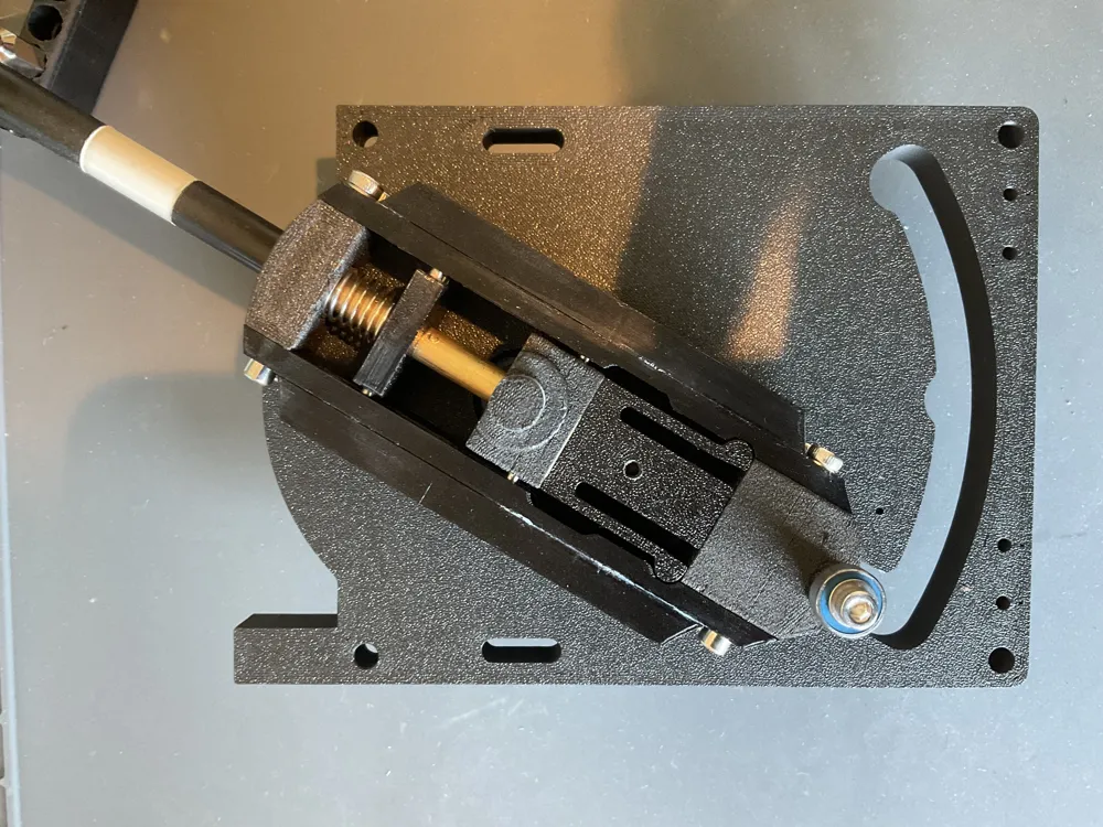
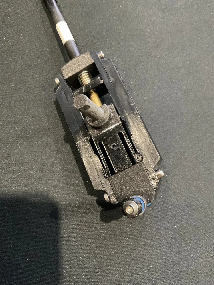
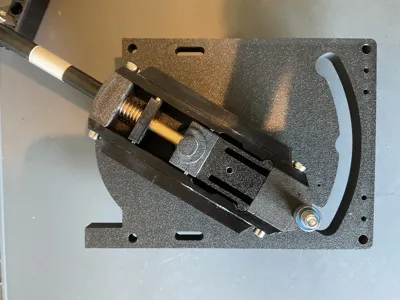
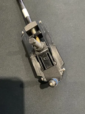
- Build the Pivot & Notch Mechanism
- Glue Side Strengthening Bars (22) to the Notch Body Sides (18)
- Glue 4 x 2mm guide pins into printed Spring Stop (19)
- Glue Pivot Body (20) to Pivot Body Detent (21). Pips and holes are included for alignment
- Glue 4 x 2mm guide pins into printed Pivot body
- Fit outer metal shaft into Notch Body Upper until flush with bottom and retain with 3mm grub screws
- Fit inner brass rod through Pivot Body
- Slide Spring Stop (19) and Spring down top of brass shaft
- Slide brass shaft above spring into outer metal shaft and Notch Body Upper assembly
- Retain brass rod in Notch Body with 3mm grub screws. Position so doesn't stick out of top of outer metal tube
- Screw the Notch Body Upper (5) and Notch Body Lower (6) to one of the Body Sides with M3 screws
- Screw other Body Side onto Body Upper (5) and Notch Body Lower (6) with M3 screws
- Test that Pivot slides smoothly up against spring and between two notched positions. A small amount of silicon lubricant can be used if needed to increase smoothness
- Fit small Notch Bearings and printed Armed Actuator (13) to Notch Body Lower and retain with screw and washers Armed Actuator should be on same side as longer pivot shaft
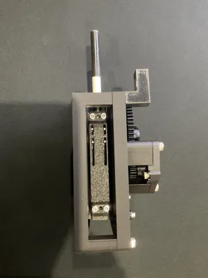
- Build Frame Assembly
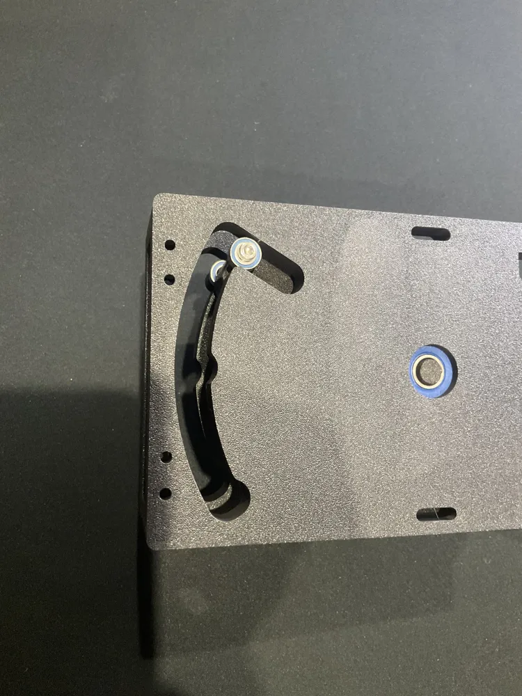
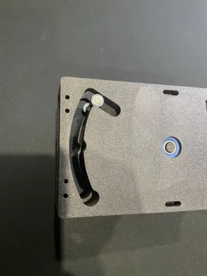
- Insert pivot bearing in Left Side Frame (07)
- Push shorter shaft of Pivot Mechanasim through bearing in Left Side Frame
- Insert pivot bearing in Right Side Frame (04)
- Push longer shaft of Pivot Mechanism through bearing in Right Side Frame
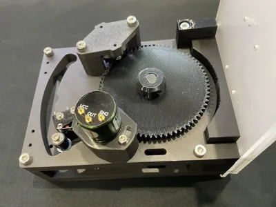
- Screw two frames together with M4 screws, including Frame Bracket (17) in top left position. This needs M4 x 30 screw to reach printed threads.
- Fit Pivot Spacer (09) on long Pivot Mechanism shaft
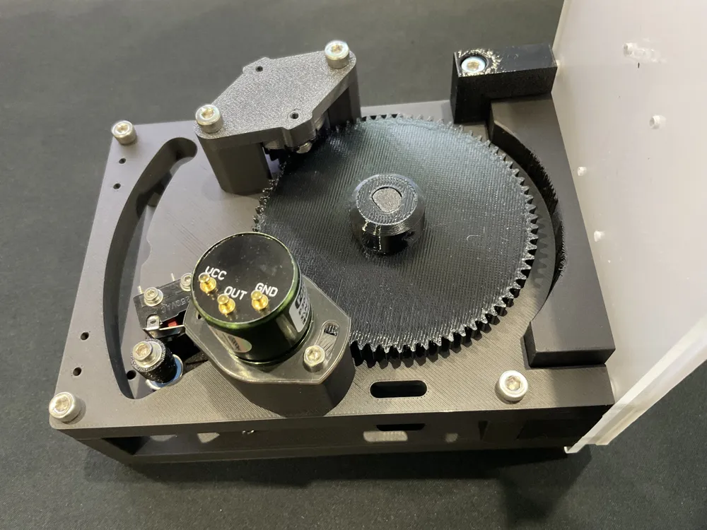
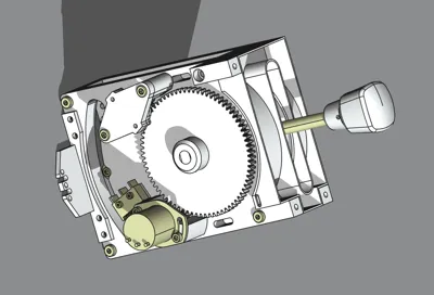
- Fit Main Pivot Gear on Pivot Shaft and retain with 3mm grub screws
- Fit Hall Effect gear on Hall Effect Sensor and retain with 3mm grub screw
- Fit Hall Effect sensor to frame with M3 screws
- Fit damper Gear (25) on rotary damper. Existing gear will need to be prised off with flat blade screwdriver. Gear should be a tight fit, but can be glued for additional security
- Fit rotary damper on Small damper Adapter (24) with M3 screws
- Fit damper and adapter on frame with M4 screws
- Fit Microswitch for Arming to frame with M2 screws
- Add optional Cable Support (14) at bottom of Right Side Frame with M3 screws
- Assemble onto Panels
- Fit LEDs into LightBox (12) and Slot Light Box (16). LED COB strips work well.
- Fit Slot Light Box (16) at top of frame. Can be glued in place, but will be trapped in place by panels
- Screw frames onto Panels with M4 screws
- Glue Lightbox in place. Pips and holes are provided for alignment
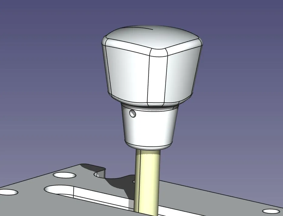
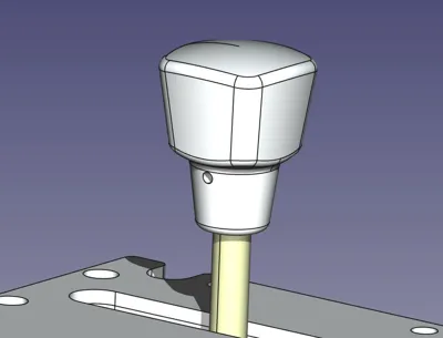
- Fit Speedbrake handle and retain with M3 grub screws
Design uses M3 and M4 cap head hex screws and M3 grub screws for assembly, plus the following parts which are all available from Amazon and B&Q in the UK, plus Ali Express as of July 2025. The rotary damper is not always available from Amazon, so I have included another source (US based).
Rotary Hall Effect Angle Sensor:
MicroSwich: The first or second one with a short flat lever:
Bansbach Easylift FRT-C2-201G1 Rotary Damper:
https://www.amazon.co.uk/Bansbach-Easylift-FRT-C2-201G1-Dampers-Standard/dp/B01N0VYKRV/
OR
https://www.mscdirect.com/product/details/14148480
22mm x 8mm x 7mm Sealed Bearings:
https://www.amazon.co.uk/gp/product/B08H2853D3/ref=ppx_yo_dt_b_search_asin_title?ie=UTF8&th=1
10mm x 5mm x 4mm Sealed Bearings:
https://www.amazon.co.uk/gp/product/B082PQ6VNJ/ref=ppx_yo_dt_b_search_asin_title?ie=UTF8&psc=1
Compression Spring from spring kit:
https://www.amazon.co.uk/gp/product/B000QF7JTO/ref=ppx_yo_dt_b_search_asin_title?ie=UTF8&psc=1
8mm outer diameter 95mm long steel tube:
6mm diameter 205mm brass rod:
https://www.amazon.co.uk/dp/B09BPMWRZC?_encoding=UTF8&ref=cm_sw_r_cp_ud_dp_0B2N3QXQQJB27KEEJ92N&
2mm Pins:
https://www.amazon.co.uk/gp/product/B07M63LBSQ/ref=ppx_yo_dt_b_search_asin_title?ie=UTF8&psc=1
Any questions, or problems with assembly, just ask.
Mark
License

You shall not share, sub-license, sell, rent, host, transfer, or distribute in any way the digital or 3D printed versions of this object, nor any other derivative work of this object in its digital or physical format (including - but not limited to - remixes of this object, and hosting on other digital platforms). The objects may not be used without permission in any way whatsoever in which you charge money, or collect fees.


Comment & Rating (29)