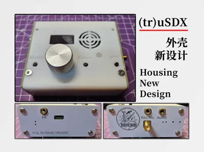
(tr)uSDX Enclosure Redesign


Print Profile(1)

Description
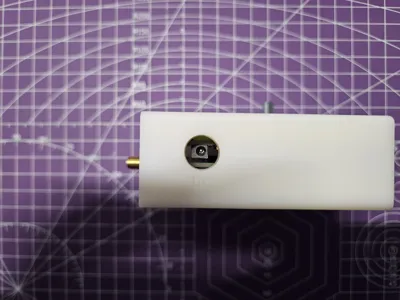
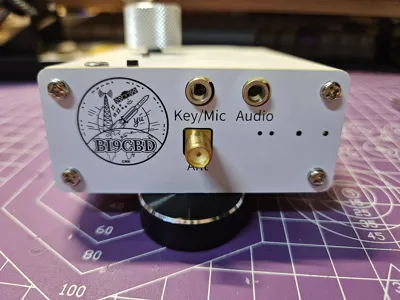
This model is a reimagining of PE1NNZ and DL2MAN's Housing for (tr)uSDX QRP Transceiver, retaining the original's port locations while significantly altering the structural design and mounting method. Nylon standoffs, screws, and slots replace the original model's PCB locating slots, simplifying assembly and potentially enhancing aesthetics.
Boost Me (for free)
Thank you for your support! May your signals reach far and wide, your voice clear across the continents, 73!
The model files include the main body, left and right panels, and bottom sliding cover, ready for printing and assembly.
You will need these additional components: M3*11 double-ended standoffs x4, M3*6+6 single-ended standoffs x4, M3*15 screws x4, M3*5 screws x8, M3 heat-set nuts x8. The standoffs are hexagonal nylon; the M3*15 screws are stainless steel, flat-head; M3*5 screws of 4-10mm length are suitable; and the M3 heat-set nuts, with inner/length/outer dimensions of 3*8*4.2 or 3*3*4mm, fit in the 10mm deep recesses.
The Speaker-Carrier remains from the original model and can be downloaded from https://www.printables.com/model/103619-housing-for-trusdx-qrp-transceiver/files.
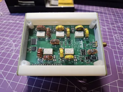
This design incorporates a 3D-printed main body, PCB side panels, and a transparent acrylic bottom cover, allowing for personalized designs and visibility of the ferrite core. The PCB panel files (Gerber format) are available separately. The transparent acrylic cover, measuring 59*85mm, can be easily cut with a craft knife or similar tool and requires no complex customization.
Assembly Instructions:
- Press the M3 heat-set nuts into the main body;
- Attach the M3*11 double-ended and M3*6+6 single-ended standoffs to the main board with the ferrite core, placing the double-ended standoffs on the ferrite core side;
- Mount the two (tr)uSDX PCBs together (not the side panels);
- Attach the Speaker-Carrier protrusions to the corresponding locations on the main body;
- Use M3*15 screws to secure the (tr)uSDX assembly to the main body, inserting knobs and buttons into their respective openings;
- Attach the bottom sliding cover;
- Use M3*5 screws to secure the left and right panels into place.

Comment & Rating (0)