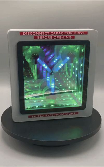
Flux Cap Infinity Mirror


Print Profile(1)

Description
Description
Intro
I was standing on the edge of my toilet trying to hang some LED art on the wall and I fell off, hit my head and then I thought I would release an INFINITY MIRROR version of the flux capacitor that can be printed with lights installed for the full effect. Wiring on this thing is relatively difficult because there is limited space but with a little patience you'll be just fine. Parts list will be dropped at the very bottom of these instructions. Good luck and may the Schwartz be with you!
Printing
If you use the 3MF file provided there should be nothing to worry about but if not there are a few things I did on these objects to print at a higher quality. Color of each part is on the plate description. This does not matter if you plan on painting and using whatever color you have on hand. The main body has 7% infill and some painted on tree supports because I didn't like how it turned out when I just enabled support straight up. The plugs have painted on tree supports as well.
*- special note for lenses: infill/wall overlap was set at 30% because 15% default meant that the bridge didn't actually connect and failed every time, bridge direction was set at 45°. Any other way I did it, it failed. For the label, I have the font sticking up enough to where if you don't want to print with red base/white top(multi filament) you can print in white, paint red, let it dry, then sand off the red paint to give it the correct effect like the original.
WLED flashing
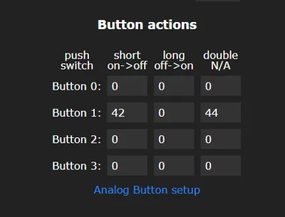
‘Flash’ the microcontroller(C3) with WLED firmware. Simply plug it into your computer and go to https://install.wled.me/ (with MS Edge) and click install and select the appropriate port that your microcontroller is plugged into. If you need help with this you can always go to the knowledge base on that website for further instructions and/or the WLED discord. Super helpful folks there. Enter in your Wi-Fi credentials after flashing the unit and now you will have access to the user interface. Click Config tab, then click LED Preferences. Change the ‘Length’ to 37 LEDs. Under button 0 click unused and disabled. For button 1- gpio- 7, pushbutton. Click Save on top then back. Find the ‘Segments’ area and under ‘Seg 0’ set stop LED at 31, then add segment for the rest. Click on ‘Seg1’ (so it has a check mark), go to the effects tab and choose Chase 2, choose the appropriate color which is an off white, turn the speed up all the way and the size to about 27. That will give you a pretty close approximation to the original but you can adjust it to your liking. ‘Seg 0’ can be anything you like. Save this as a preset and have it ‘apply at boot.’ Feel free to use any of the cool effects in the library and even create a playlist! Remember, its battery operated so the brighter you make it the less time it will run. I set mine at 40 on the brightness slider. Now head over to ‘time and macros’ and scroll down to button #1. For ‘short on→off’ type in 20, ‘long on→off’ 0, ‘double N/A’ 21. Save. Back up to the main page and add a preset. Set it as ID 20, enter in NextFX as the title, uncheck ‘use current state’ and in the text box for ‘API command’ enter in ‘win&P1=1&P2=19&PL=~’ with no quotes. Now you can add a bunch of presets and when you push the momentary button it will cycle through presets 1 through 19. Create a playlist if desired and set that to ID #21 so that when you double press on the momentary button it will enable that playlist. This is optional. Screenshots for all this included.
Assembly
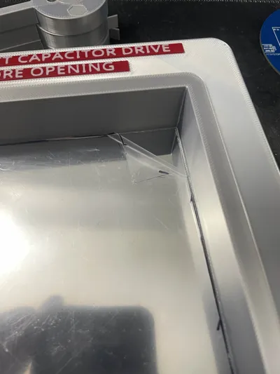
Paint as necessary first and let it dry. Use the picture provided as a guide. Use the mirror template to trace out the internal mirror piece and cut with scissors. Peel and stick to base. Peel top film off(careful, don't scratch or smudge the mirror!) Use a hot soldering iron tip to melt thru the wire holes from the back. Now jump to the wiring section and come back here when done. ___ After completing the wiring you can finish gluing all the rest of the pieces on the unit and controller module can be glued into the module compartment, along with the lid, to prevent movement when you plug it into charge. Be careful when cutting the one way mirror as it's thicker and tends to fracture easily on the edges. Also superglue tends to be stringy and will mess up the mirrors if allowed to drip on them.
Wiring
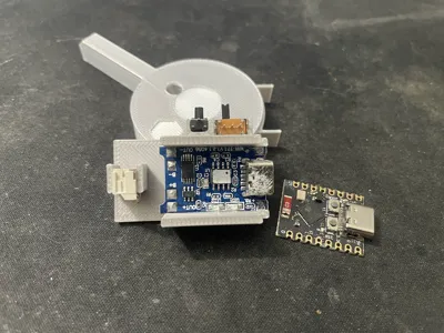
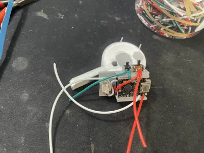
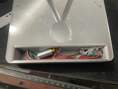
I provided a nifty little frame that can house an ESP32 C3 controller, a charging module, momentary button, slide switch, and PH 2.0mm plug. This gives us the option to use this as a stand alone battery operated unit. The 2.7mm LED strips are difficult to work with because of the small size and fragile nature. The LED strip itself will already come with the starting end wired up, so you can just cut the plug off but keep the wires as long as possible. Cut the strip at the solder pads at 6 LEDs length (pic). You will need to make two more strips. The solder pads on the bottom side will have a little bit of adhesive from the double sided sticky tape you'll need to gently scrape off so that you can tin the pads. Make sure after soldering the three wires on the ends(5+ red, GND white, Data green) that you put some heat shrink tubing(see pic) over the soldered end to strengthen the connection. Otherwise, they will break the pads off very easily. Make the wires long, around 150 mm or 6 inches so you have plenty to work with. You'll be cutting a lot of it off but you don't want to short yourself. Insert the soldered strips through the back and attach them to the front side(see pic), leaving room for the lenses to go over it. On the backside, cut all of the red wires evenly to be able to sit inside the larger portion of the cavity . Strip the ends(about 10 mm) and twist them all together along with one additional red wire, which will be fed into the controller assembly compartment. Solder them together. Do the same with the white and green wires. Use electrical tape or heat shrink tubing for protection of the bare ends. Feed all 3 wires into the assembly compartment. For the perimeter LED strip, solder the correct colored wires to to the ‘in’ side(red, green, white) and one green wire to the ‘out’ data side. This wire(the ‘out’ wire) should be soldered to the green wire that feeds the three smaller LED strips. Direction of flow is important here.
Glue in the switch, button, charge board(into the bottom slot), and PH 2.0mm plug as pictured. DO NOT USE TOO MUCH GLUE or you will glue the switches open or closed! Color coding the wires will be helpful so as to not get confused. White for ground, red for 5 V+, green for data signal(GPIO2).
Now inspect the battery's plug orientation against the mounted plug to verify - and + side. Solder a white/red wire(see pic) from B- and B+ of charging board to the corresponding pins of the PH 2.0mm connector (make these wires as short as is reasonable). CHECK THIS TWICE as it's VERY important! China has been known to ship batteries that are not orientated the same as a previous batch. Now solder a red wire from OUT+ of charge board to one side of the switch(cut to length and make it as short as possible). Solder one end of another red wire (about 50mm) to the middle pin of the switch. Leave other side wild(unconnected) for now. Solder a 50mm white wire to the OUT- of the charge board. Leave the other side wild.
Before inserting the microcontroller to the top slot, solder a 50mm red wire to ‘5V’ pin, 50mm white wire to G pin, 50mm green wire to the GPIO2pin, and another 50mm green wire the GPIO7 pin(for button) and strip the ends about 8mm. Slide the microcontroller in the top slot(see pic). Now twist the red wires from switch/5V pin/LED strip and solder them together. Do the same with the white wires from OUT- of charge board/G pin/button/LED strip. Solder the green wire from GPIO2 to the green data wire of the LED strips. Solder the green wire from GPIO7 to the button ( make sure to solder it to the correct tab which is indicated in the picture). Protect the bare ends with electrical tape or heat shrink tube(see pic).
Now for the fun part. Plug in the battery and test function of switch, button, and LEDS. Once confirmed all is working, you can glue the lenses on. On the compartment side, gently push the wires into place and check the lid to make sure everything fits properly. You can now finish assembly by gluing the rest of the parts into place.
If you have any questions feel free to comment and I'll try to help out as best I can. Good luck and remember it's best not to show yourself to your other self when you go back in time or the universe could implode!
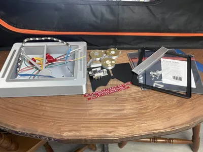
Parts List
( some links may be invalid due to stores opening and closing all the time or products no longer available. Feel free to source your own material)
ESP32 C3 controller- https://www.aliexpress.us/item/3256805781327184.html
WS2812B LED strip(160/m pitch)- https://www.aliexpress.us/item/3256806510961905.html
WS2812B Black 30/m- https://www.aliexpress.us/item/2251801850504415.html
102050 battery(with PH 2.0mm connector. - https://www.aliexpress.us/item/3256808598701583.html
Slide switch(5mm)- https://www.aliexpress.us/item/3256806149664764.html
Charger board(USB C)- https://www.aliexpress.us/item/3256806441171319.html
PH 2.0mm connector(2 pin)- https://www.aliexpress.us/item/3256802283569294.html
22 AWG LED 3 wire- https://www.aliexpress.us/item/3256801728933470.html
Momentary button (5.5mm) https://www.aliexpress.us/item/3256805639981565.html
Adhesive mirror- https://a.co/d/gBXxnM7
40% one way mirror- https://a.co/d/1qbwoUS
Comment & Rating (0)