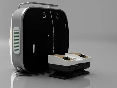
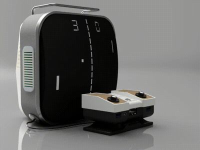
Mini TV and its Pong Power Bank


Print Profile(1)

Description
Project: Retro Console Transformed into a Custom Power Bank (Calicie 3D)
🌐 Calicie 3D Presentation
Calicie 3D is me: Cécilia, a passionate creator and tinkerer! - 📆 I've been modeling for over 2 years. - 🌐 I started 3D printing less than a year ago, and it's a revelation! - 🎨 This console is my very first published model integrating electronics.
🛠️ Project Details
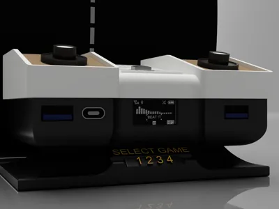
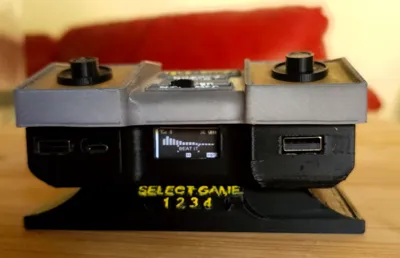
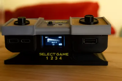
Objective: Create a mini retro console usable as an 8,000 mAh power bank with USB-A & USB-C ports, a front-facing OLED screen, an ON/OFF switch reusing the original button, and an LED strip integrated into the television.
🔧 Printing Materials
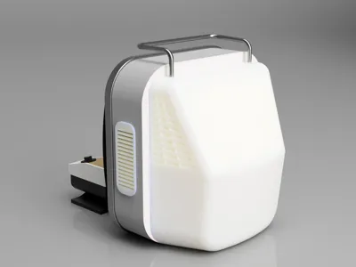
- Basic PLA: for the entire case, and most of the television
- Translucent white/black PLA: for the simulated TV screen (with the engraved, backlit Pong visual)
✉️ Electronic Components (2x 21700 batteries)
| 🔹 Component | 📏 Role |
|---|---|
| 2x 21700 Batteries - 4000 mAh | Main power source (8,000 mAh total) |
| 1x 2S 5A BMS | Protection for charging/discharging the 2 cells |
| 1x ZK-5V04 Boost Module | Converts 3.7V → 5V, 3A, with USB-A & USB-C outputs |
| 3x Recessed female USB-A | 2x on the front, 1x on the back |
| 2x USB-C breakout board (5.1kΩ) | For USB-C output (front) and charging input (back) |
| 1x 0.96” SSD1306 white I²C OLED | Displays battery status on the front |
| 1x SPST switch (ON/OFF) | Connected to the original physical button (top left) |
| 5V RGB LED strip (USB or direct) | Backlights the Pong engraved screen from the inside |
🔌 Simplified Wiring Diagram
Main power supply: - The 2x 21700 batteries are connected in parallel to the 2S BMS - The BMS output powers the ZK-5V04 boost module (which manages USB-A and USB-C)
Connections: - The USB-A outputs (front + back) are soldered directly to the boost module - The USB-C are connected via breakout boards (front output, rear input) - The OLED is powered at 5V via the boost, and connected via I²C (SDA/SCL) - The ON/OFF switch cuts the power between the batteries and the BMS - The white LED strip is connected to a 5V USB output.

🎡 Constructive Feedback
This project is a complete experiment for me, and I am open to any constructive ideas: - Possible improvements in component selection? - Internal fastening ideas or cleaner distribution? - Electrical or aesthetic optimization?
Thank you in advance to those who take the time to share their feedback or advice!
Comment & Rating (4)