
Adjustable Phone Stand Tripod, Desk or Photography
Print Profile(7)


Description
Membership
You can sell this item with a commercial membership!
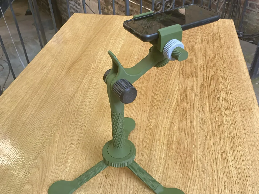
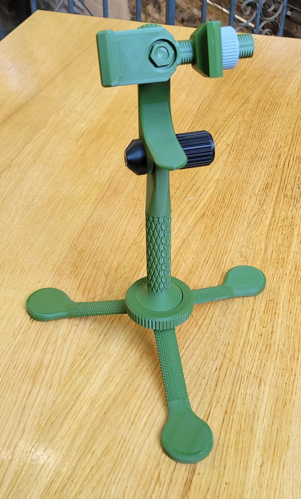
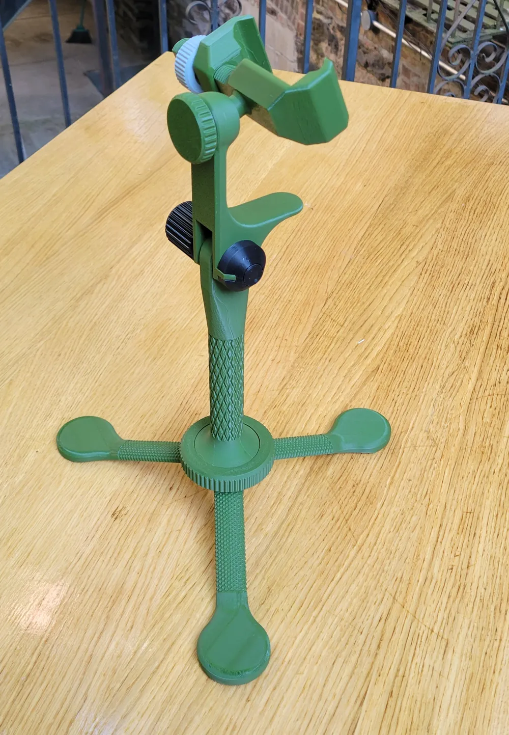
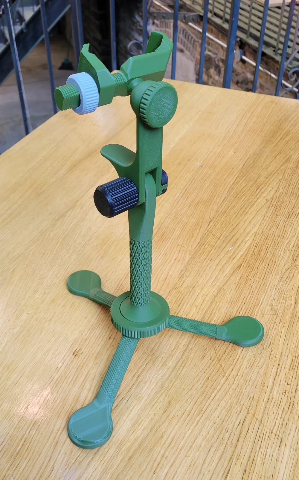
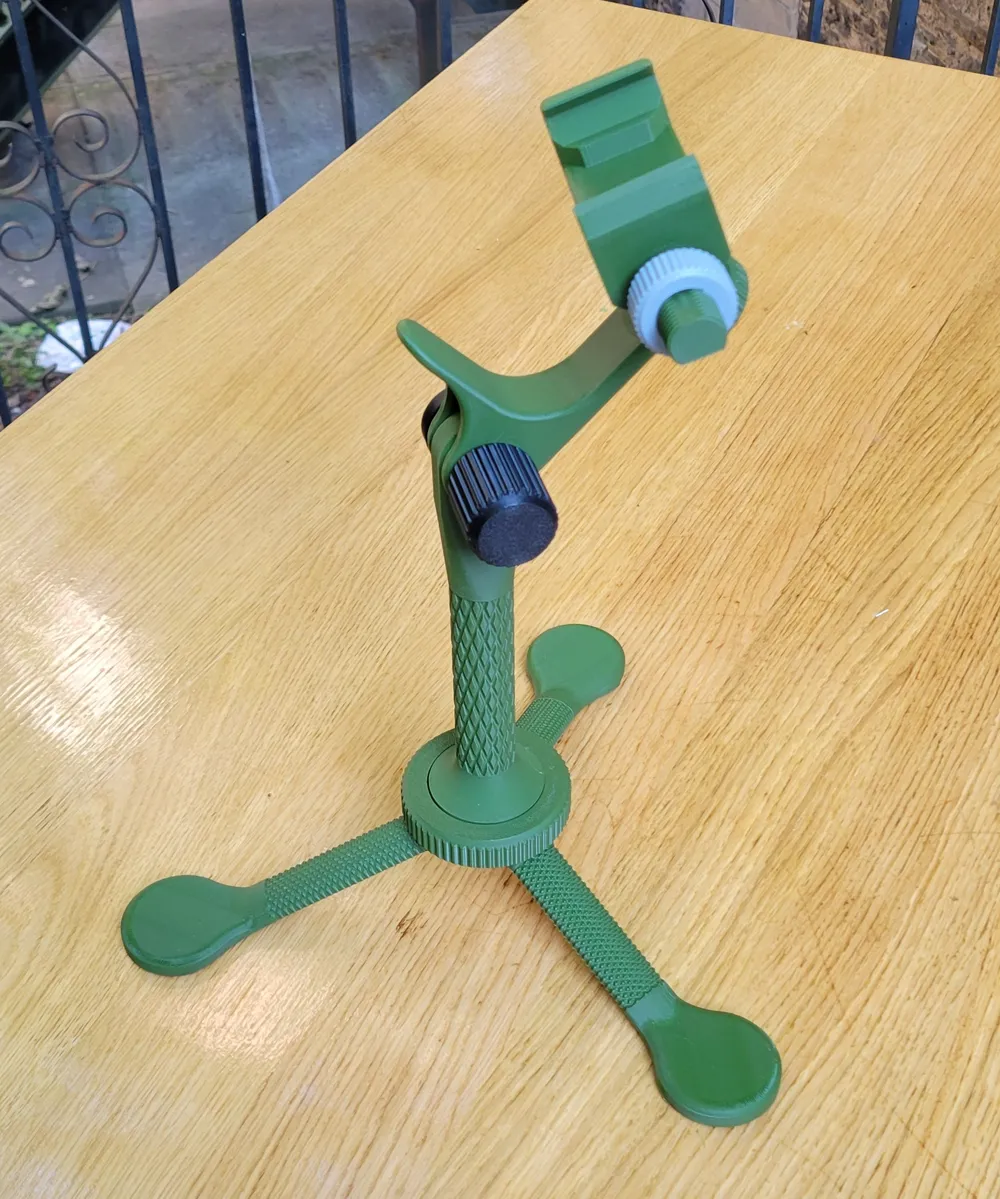
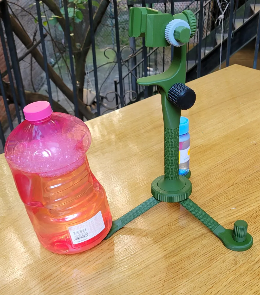
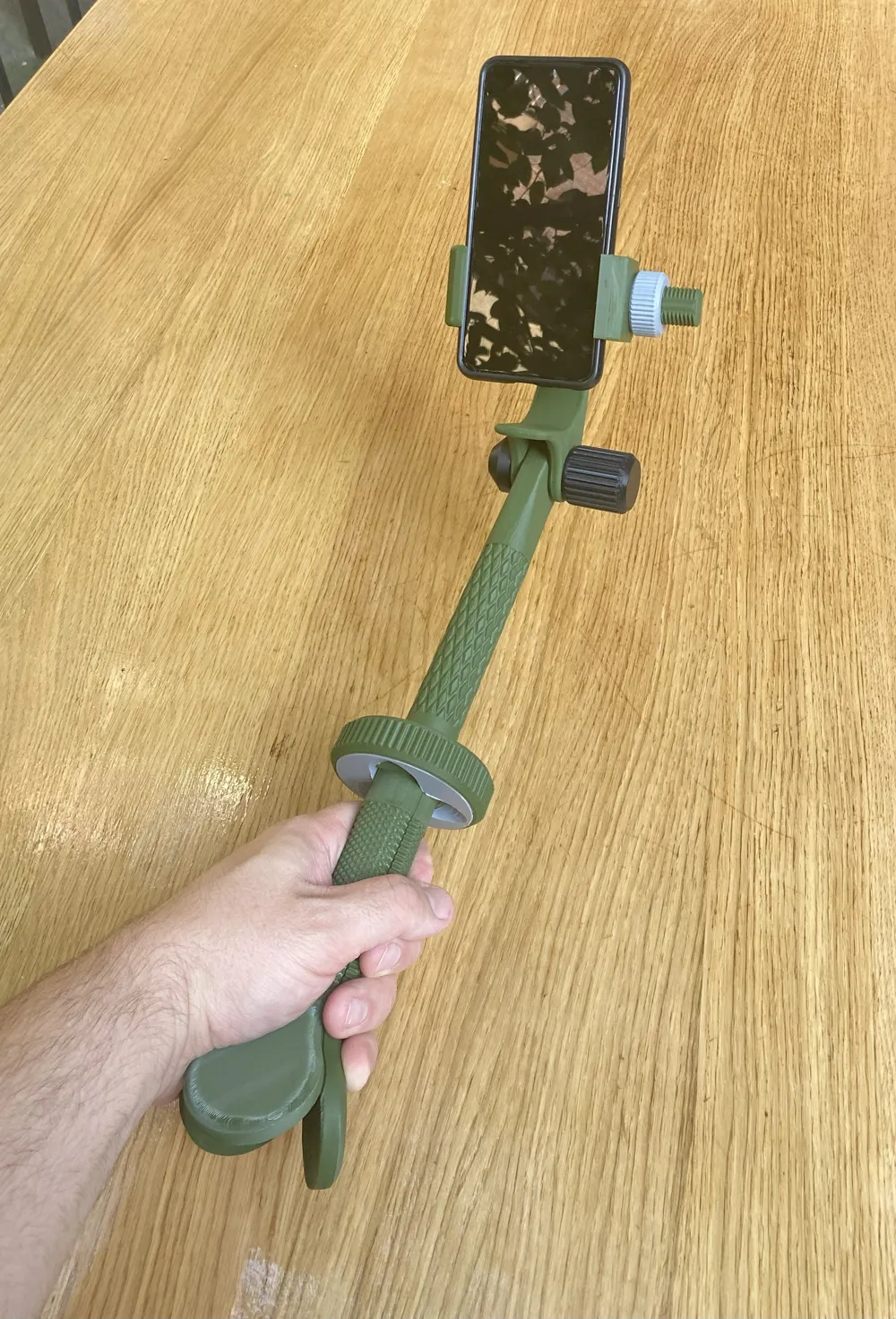
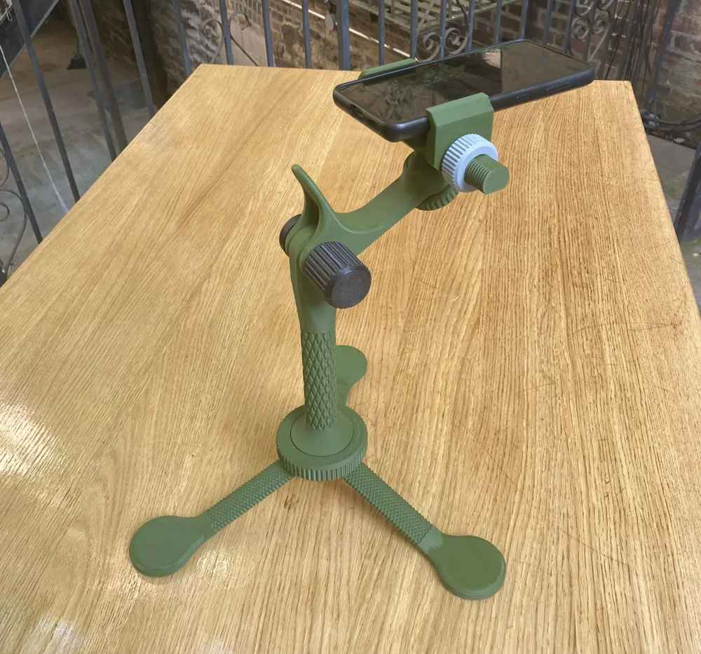
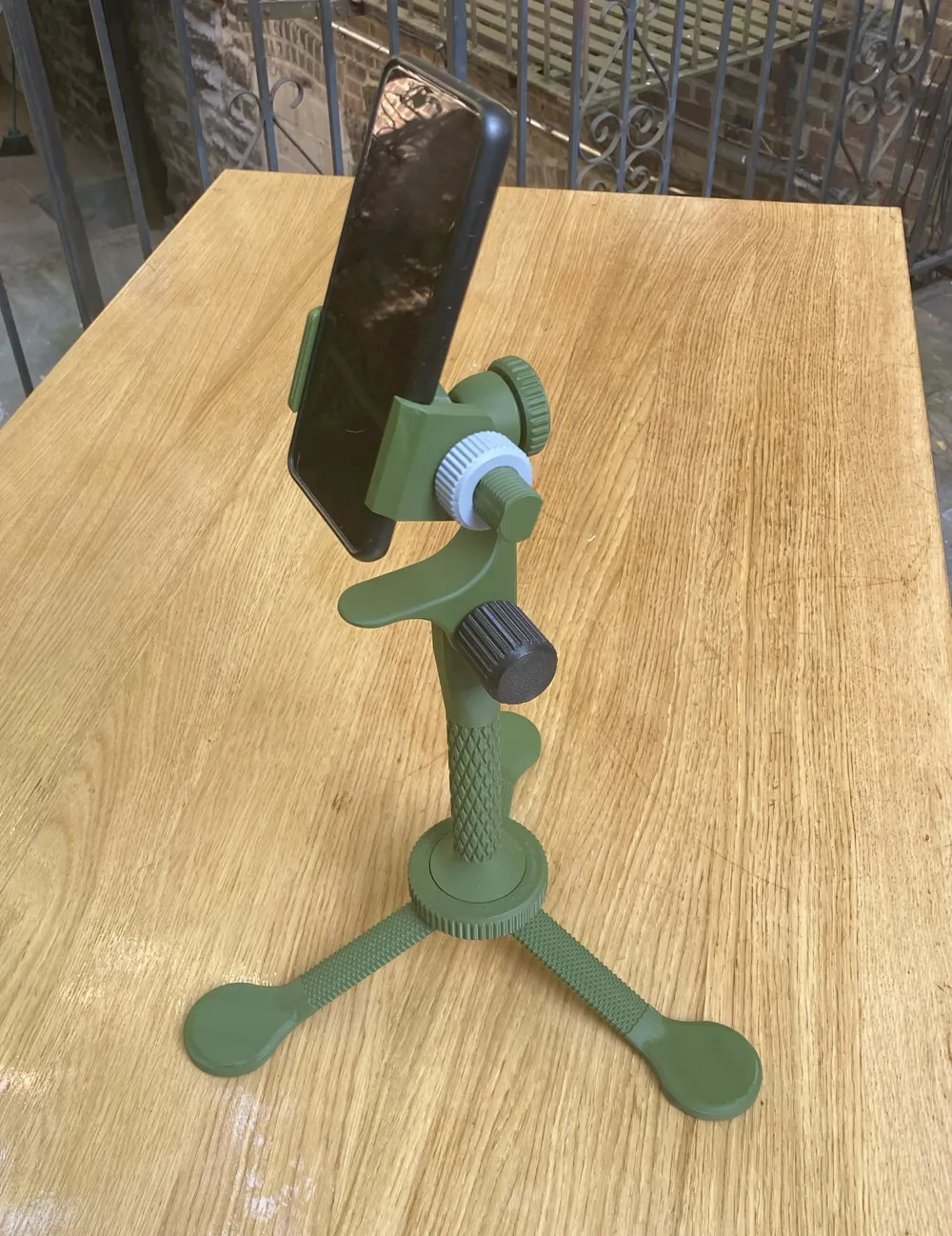
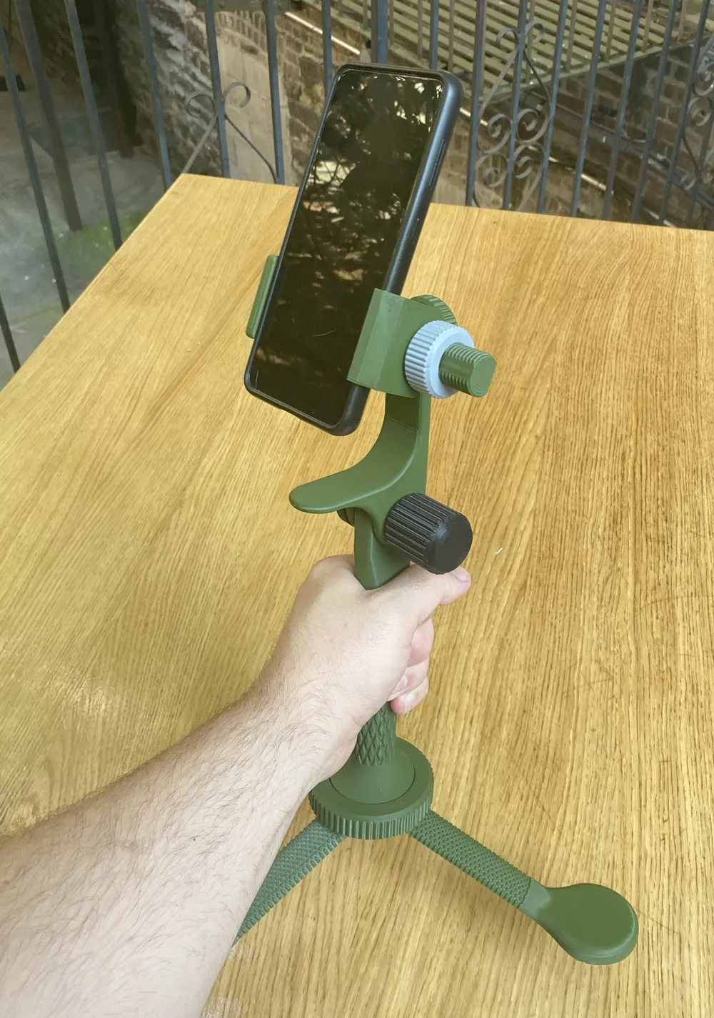
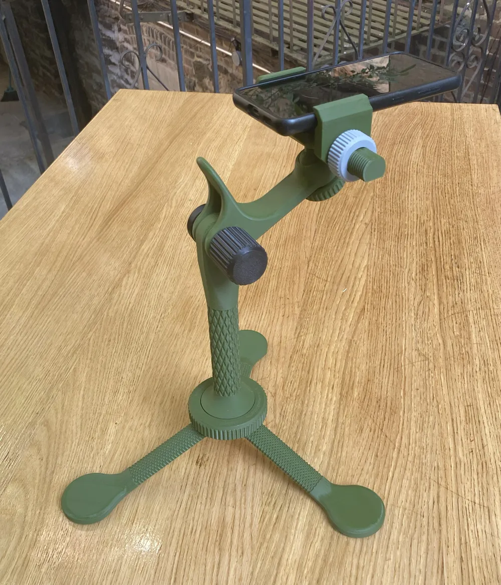
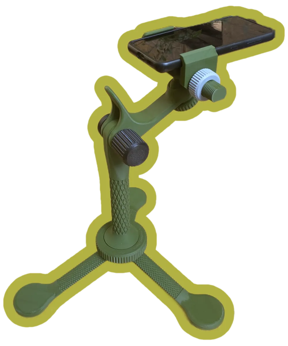
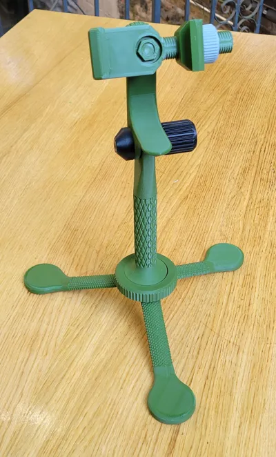
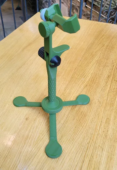
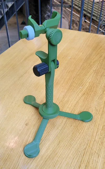
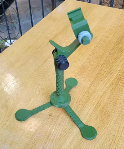
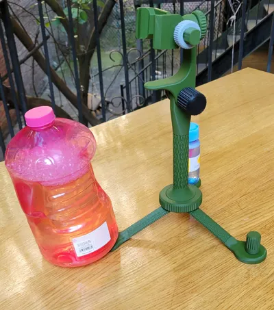
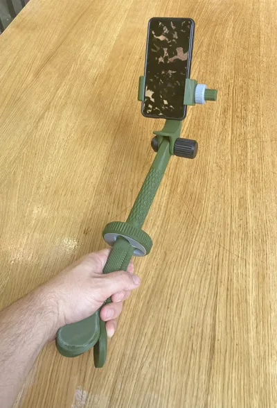
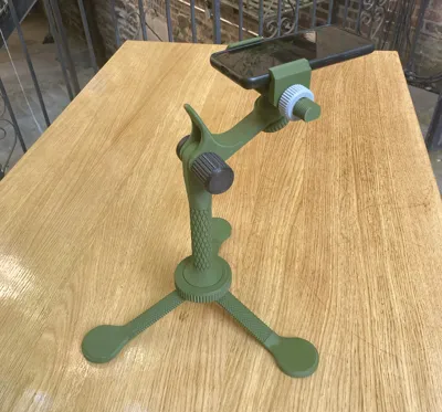
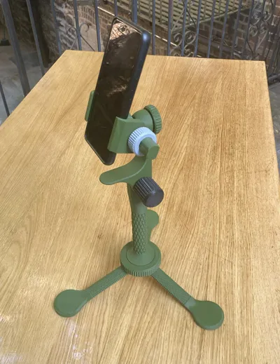
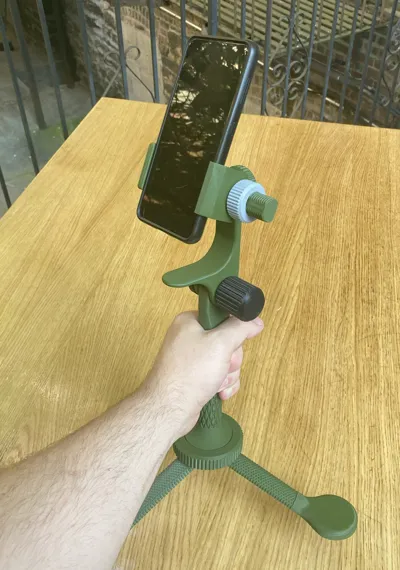
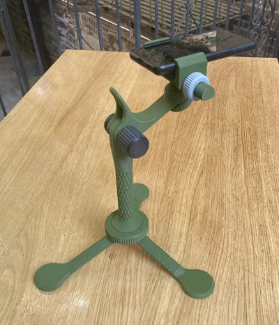
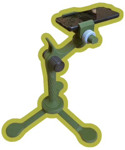
Here is my take on a sturdy versatile tripod for phone photography.
Features:
Nice wide tripod base
twist, pivot, and swivel adjustments
selfie stick
stabilization
tool included
textured grip areas
fully 3d printed
There are a few fits that i made tight intentionally (0.1mm), but there is clearance everywhere and everything goes together well.
Dry your filament
clean your bed
use glue
calibrate your filament
Assembly process:
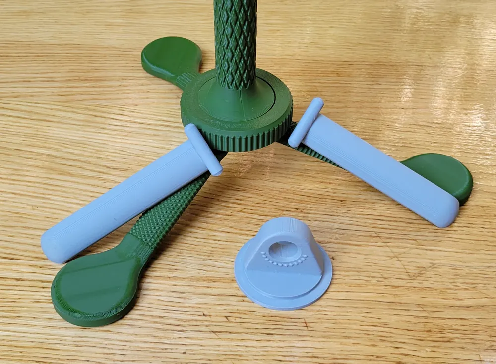
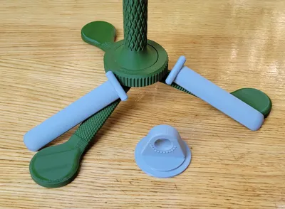
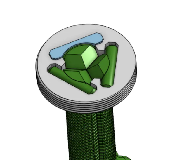
- Insert the “legs” into the “leg pivot ring”, one at a time. You may need to rotate and angle the legs to get the pivot side through the ring. seat the pivot portion of the leg in the slots as shown in the picture below. Then place a “leg friction” piece on top of each leg pivot as shown in the image below.
2. Select either the “tilt” part or the “extended tilt column” and place it on top of the assembly from the previous step. Then place the “tilt lock” ring over the leg pivot ring screwing the two together. make sure no other pieces fall out of place while tightening the ring down.
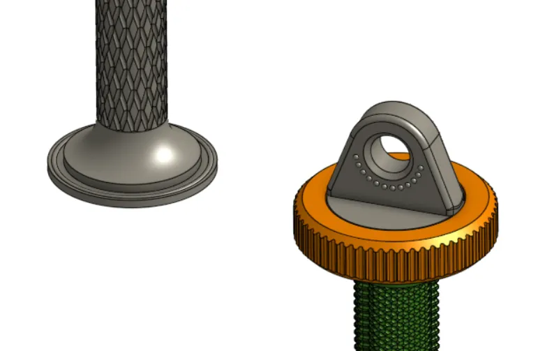
3. Place the “mount arm” onto the previous assembly and align the holes. insert the “arm lock” through the hole in the “mount arm” screwing into the “tilt nut” as shown in the image below.
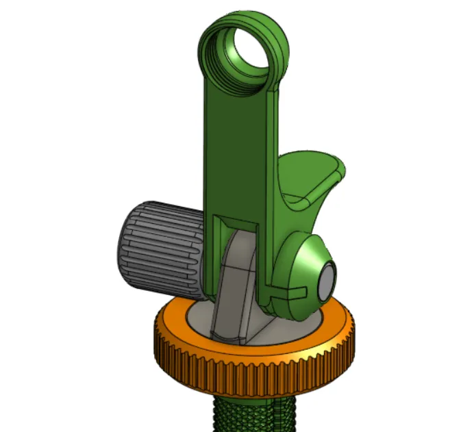
4. insert the “ball dowel” into the “ball screw” and cap with the “ball bottom” as shown in the image below.
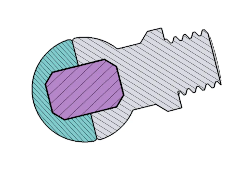
5. Insert the previous ball assembly into the previous mount arm assembly and screw the “ball tension knob” in as shown in the image below.
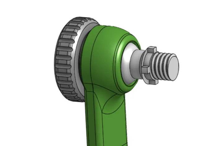
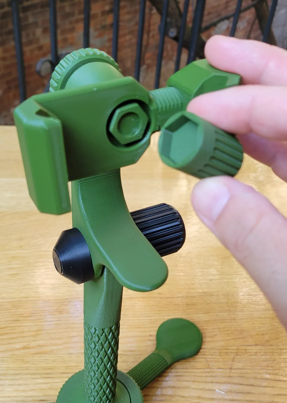
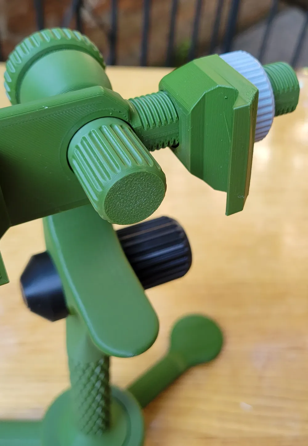
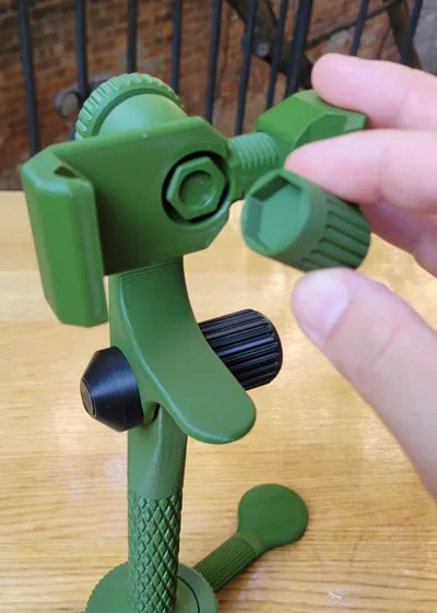
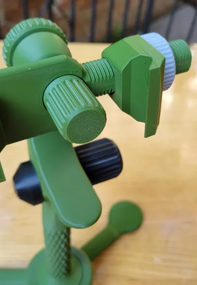
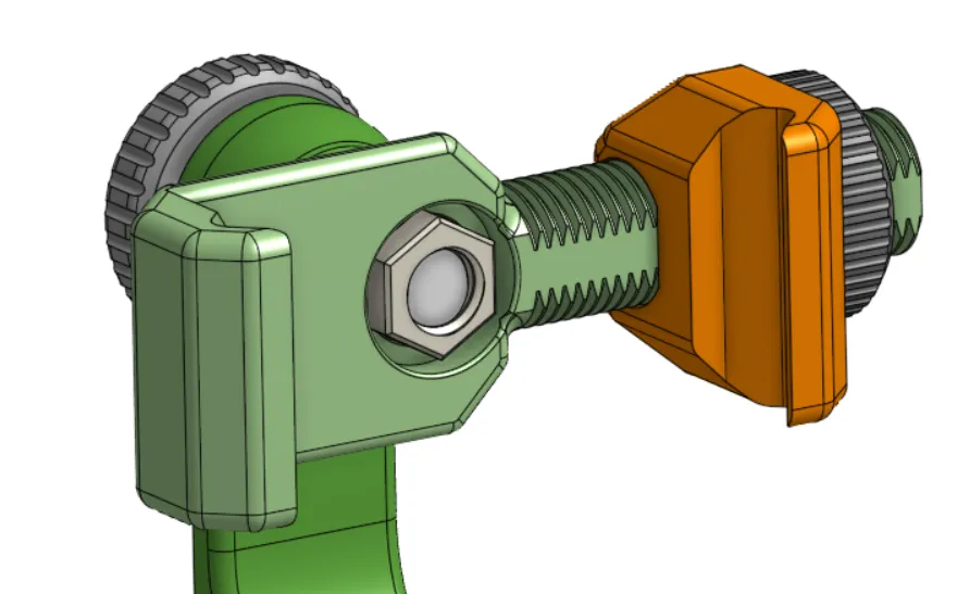
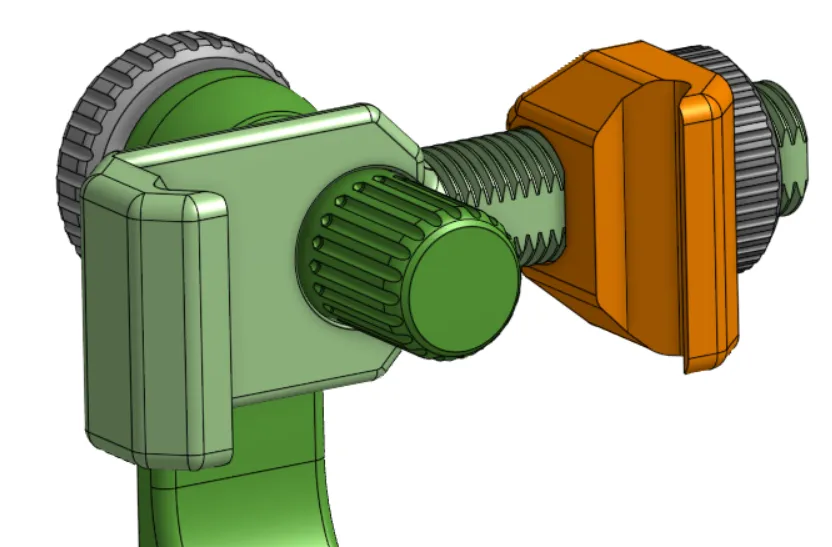
6. Place claw 1 onto the ball screw and secure with the “claw to ball nut” using the “tool” to tighten. slide "claw 2" over “claw 1” and screw the “claw nut” down as shown in the images below.
License

You shall not share, sub-license, sell, rent, host, transfer, or distribute in any way the digital or 3D printed versions of this object, nor any other derivative work of this object in its digital or physical format (including - but not limited to - remixes of this object, and hosting on other digital platforms). The objects may not be used without permission in any way whatsoever in which you charge money, or collect fees.


Comment & Rating (500)