Smart Turntable and Trigger For Canon DSLR


Print Profile(2)


Description
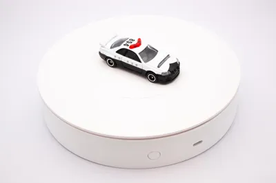
Pico-Powered Smart Turntable for 360° Photography
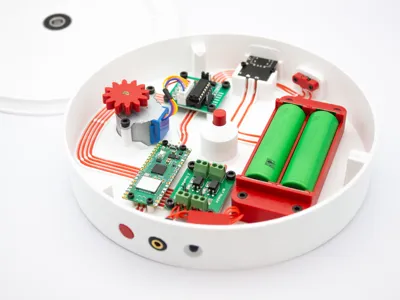
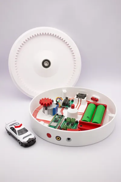
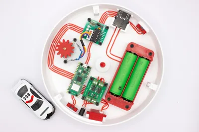
Take your product photography, 3D scanning, and photogrammetry projects to the next level with this feature-rich, Wi-Fi-controlled smart turntable! Powered by a Raspberry Pi Pico W, this project provides automated, repeatable, and precise rotational control for capturing perfect 360-degree images.
UPDATES:
- 2025-07-06: New model files. Revised clearances, fixed some bugs, fixed object orientation. Optimized some parts to print floating holes without support.
- 2025-07-06: Added a version without infrared transmitter. Added freehand wiring option for both. Also added button caps with icons for your customization.
- 2025-07-18: Big changes to the code. Added persistent way to store settings among other improvements.
- 2025-07-18: Slight change to the pinout. Old pin used ADC GPIO which might cause issues for some people. Button pin is now GP22.
- 2025-07-18: Uploaded all the code to GitHub.
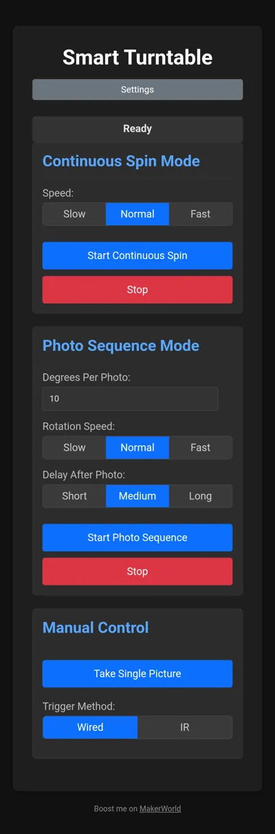
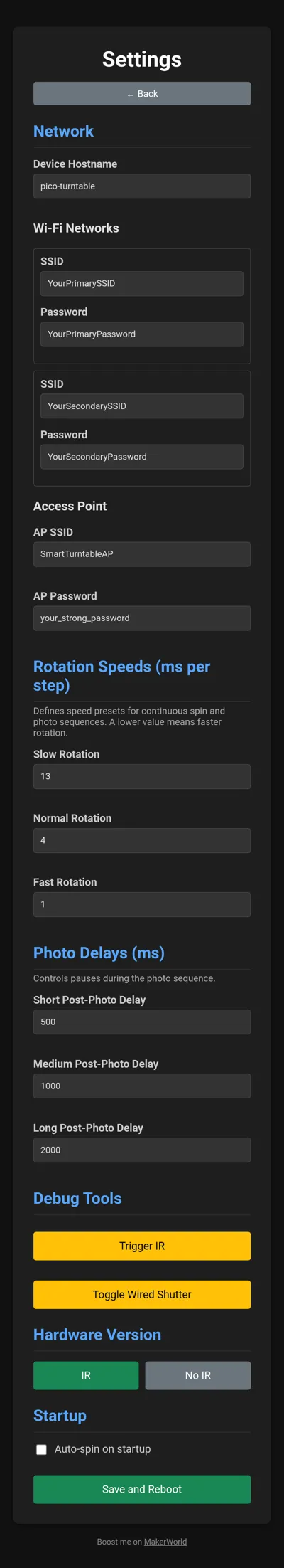
- 2025-07-18: Added screenshots of the control application.
- 2025-08-05: Added wiring diagram. Full size image can be found on GitHub.
Key Features:
- Full Web Interface: Control all functions from your phone or computer.
- Wi-Fi connection: Connect directly to the turntable or make it connect to your network. Enter your credentials to in the source code before flashing the Pi.
- Automated Photo Sequence: Set the degrees per shot and an optional delay, and let the turntable automatically rotate and trigger your camera for a full 360° rotation.
- Dual Camera Trigger: Supports both a standard wired remote (via optocoupler) and a powerful IR transmitter to work with a wide range of Canon DSLR/mirrorless cameras.
- Advanced Physical Button: A single push-button provides tactile control: a short press cycles through calibrated speeds, while a long press toggles the continuous spin on and off.
- Battery Powered: Dual 18650 batteries can power it for a long time.
- USB-C Power & Charge: Power and charge the turntable with USB-C chargers. PD is also supported!
Basic Operation Guide
- When it starts up, it looks for known Wi-Fi networks. Two networks can be predefined in the source code. I have my home network and mobile hotspot there. If it does not find any of those, it creates it's own access point which is also defined in the source code.
- Connect to the turntable (http, port 80) via it's IP or if you're lucky - hostname. Hostname is also defined in the source code.
- When it starts it automatically spins in its slowest speed. You can toggle between three predefined speeds by single clicking the button near the 3.5mm jack port.
- You can stop or start the spin by holding that button for a few seconds.
- The button on the USB-C side is the power button. Single click turns it on, double click - off.
- You can power it straight via USB-C even if no batteries are inserted. USB-C port also charges the batteries. The charge level display can be seen on the bottom of turntable.
- The web app let's you start, stop and chose between the same 3 different speeds for continuous spin.
- The “spin and trigger” feature is only accessible via the web app. It lets you set a number of degrees to spin and take a picture after. It stops after full 360 rotation.
- You can set some options for triggering such as delay after each trigger, a way to trigger (wired or IR) and whether or not to use autofocus (wired only).
Pico W Pinout

# Stepper Motor Driver (ULN2003)
IN1: GP18
IN2: GP19
IN3: GP20
IN4: GP21
# Physical Button
BUTTON_SIGNAL: GP22
# Camera Triggers
WIRED_AUTOFOCUS: GP9
WIRED_SHUTTER: GP10
IR_TRIGGER: GP13
# Power & Ground
3V3V(OUT) -> Powers button and IR circuit
GND (any, e.g., Pin 38) -> Common ground for all component
Parts List:
Electronics:
- Raspberry Pi Pico W: Available on AliExpress
- 28BYJ-48-5V Stepper Motor with ULN2003 Driver Board: Available on AliExpress
- CKCS Battery Management System: Available on AliExpress
- PC817 2 Channel Optocoupler: Available on AliExpress
- 6x6x7mm Mini Push Button Switch: Available on AliExpress
- 3.5mm PJ-392A Jack (3 pole): Available on AliExpress
- 4 Pin JST XH2.54 Male and Female Connectors: Available on AliExpress
Parts for IR Module:
- TSAL6400 High-Power IR Emitter LED: Available on AliExpress
- 20mm x 80mm Breadboard: Available on AliExpress
- 1kΩ 1/4W Resistor: Available on AliExpress
- 27Ω 1/4W Resistor: Available on AliExpress
- 2N2222 NPN Transistor: Available on AliExpress
Other:
- 18650 Spring Contacts (18.5mm): Available on AliExpress
- 22-28AWG Silicone Wire: Available on AliExpress
- PTFE Tube (4mm Outer Diameter): Available on AliExpress
- M2x6 Self Tapping Screw: Available on AliExpress
- M3x8 SHCS Screw: Available on AliExpress
- (OPTIONAL) 25mm x 8mm Steel Shaft: Available on AliExpress
Code
Disclaimer: this was coded with Gemini 2.5 Pro. I am not a programmer. I love AI for enabling me to do such things.
IR Module:
Cut the 20x80mm breadboard as pictured (6x6 segments) and proceed with assembly and soldering. Assembled module fits into the printed case. Case cover is friction fit.

Assembling the IR Trigger Module
Components Needed:
- 1x TSAL6400 IR LED
- 1x 2N2222 (or similar NPN) Transistor
- 1x 1kΩ Resistor (for the transistor base)
- 1x 27Ω Resistor if using TSAL6400 High-Power IR LED (to limit current to the LED)
- 1x 100Ω Resistor if using generic IR LED (to limit current to the LED)
- Three different colored wires (e.g., Red for 3.3V, Black for GND, Yellow for Signal)
Step-by-Step Instructions
- Prepare the Transistor:
- Hold the 2N2222 transistor with the flat side facing you. The pins, from left to right, are Emitter, Base, and Collector.
- Bend the center Base pin slightly away from the other two to make it easier to work with.
- Solder the Base Resistor:
- Solder one end of the 1kΩ resistor to the transistor's center Base pin.
- Solder the IR LED:
- The IR LED has a long leg (Anode, a positive side) and a short leg (Cathode, a negative side).
- Solder the 27Ω resistor to the LED's long leg (Anode).
- Solder the LED's short leg (Cathode) to the transistor's Collector pin (the pin on the right, when the flat side faces you).
- Solder the Connection Wires:
- Ground Wire (Black): Solder your black wire to the transistor's Emitter pin (the pin on the left). This will go to a GND pin on the Pico.
- Signal Wire (Yellow): Solder your yellow wire to the free end of the 1kΩ resistor. This will go to GPIO13 on the Pico.
- Power Wire (Red): Solder your red wire to the free end of the 27Ω resistor. This will go to the 3.3V OUT pin on the Pico.
The Story
I was working on this turntable for a while now and just a few days ago I noticed this Photography Accessories contest. I rushed it to complete before the contest closes and during the final assembly I physically damaged the Pi Pico. Therefore no screenshots of the web application, no videos of it working and no complete instructions. I did not have full code backup so you'll have to sort the dependencies as well. I'll rebuild it soon. Terribly sorry for that, but trust me, it's amazing!
I hope you appreciate the wiring. This was a horrible decision but I wanted for it to look good in photos. I think I managed that.
Please don't mind the AI description in the first paragraphs. I don't have much time, but promise to do a proper release with build instructions and wiring a bit later.
License
You shall not share, sub-license, sell, rent, host, transfer, or distribute in any way the digital or 3D printed versions of this object, nor any other derivative work of this object in its digital or physical format (including - but not limited to - remixes of this object, and hosting on other digital platforms). The objects may not be used without permission in any way whatsoever in which you charge money, or collect fees.
Comment & Rating (30)