
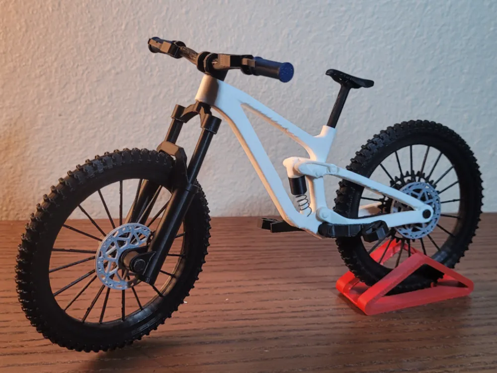
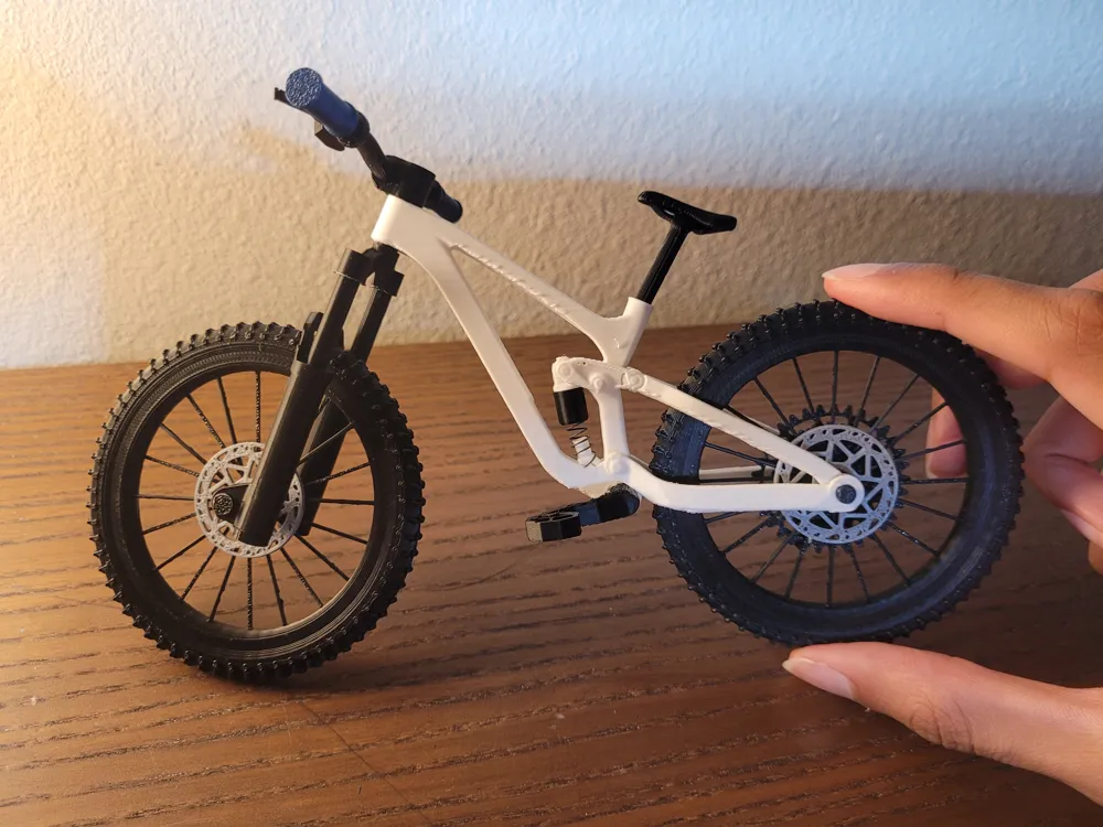
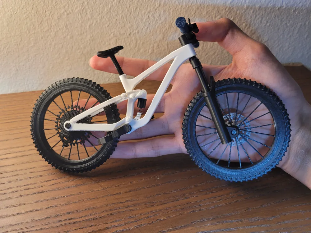
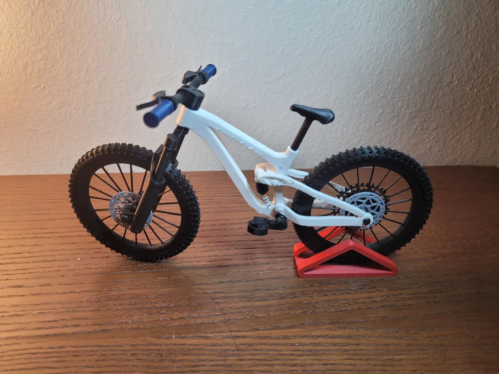
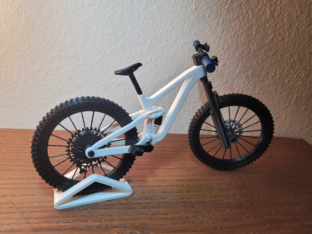
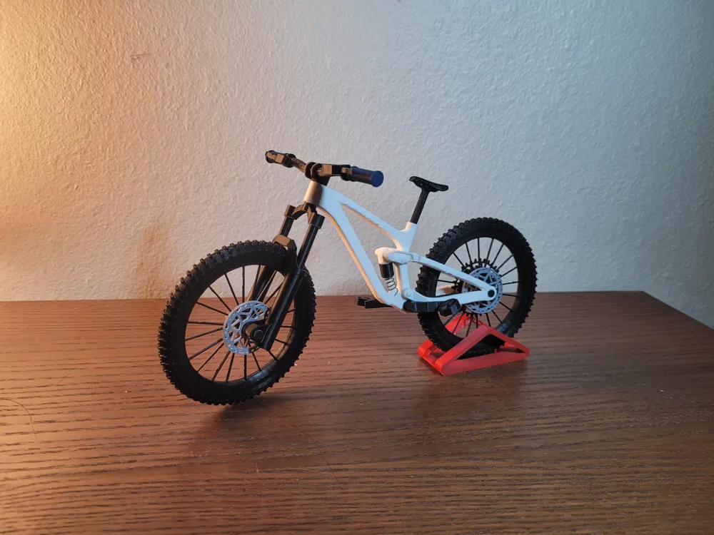
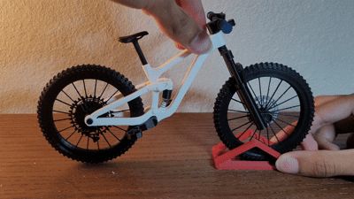
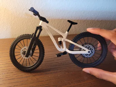
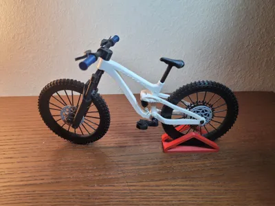
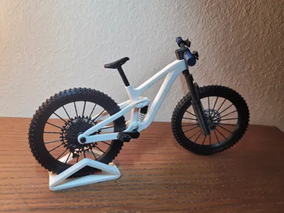
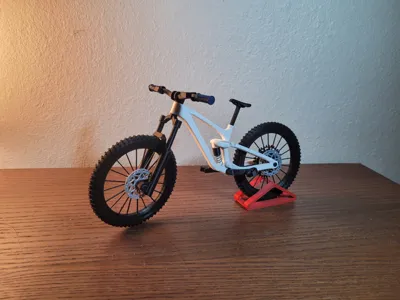
Full Suspension Model Mountain Bike (enduro bike)

Print Profile(4)



Description
Membership
Become a commercial member today! Subscribe and be able to legally sell physical prints of my models!
Boost Me (for free)


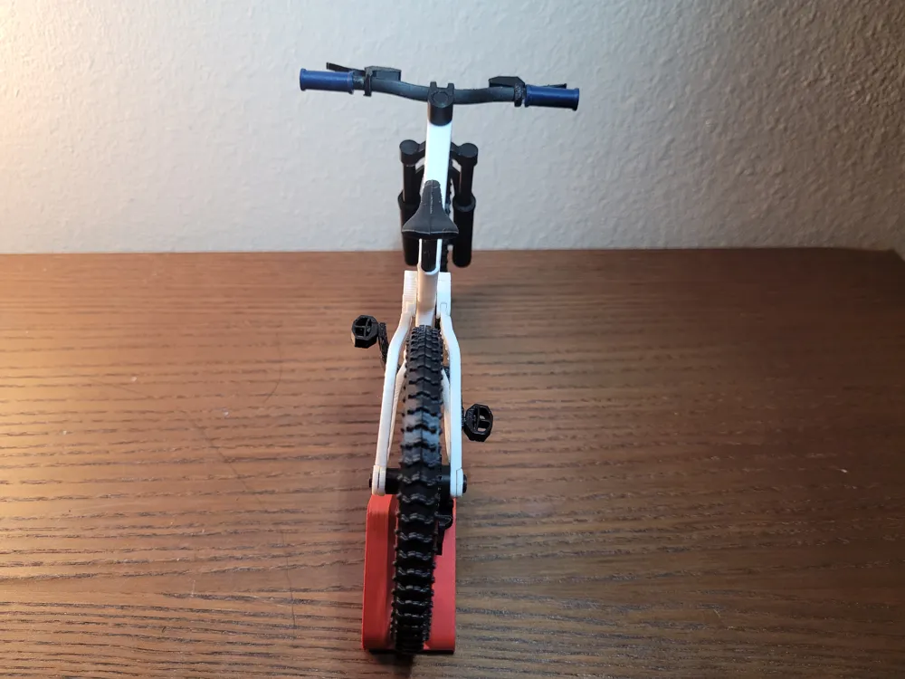
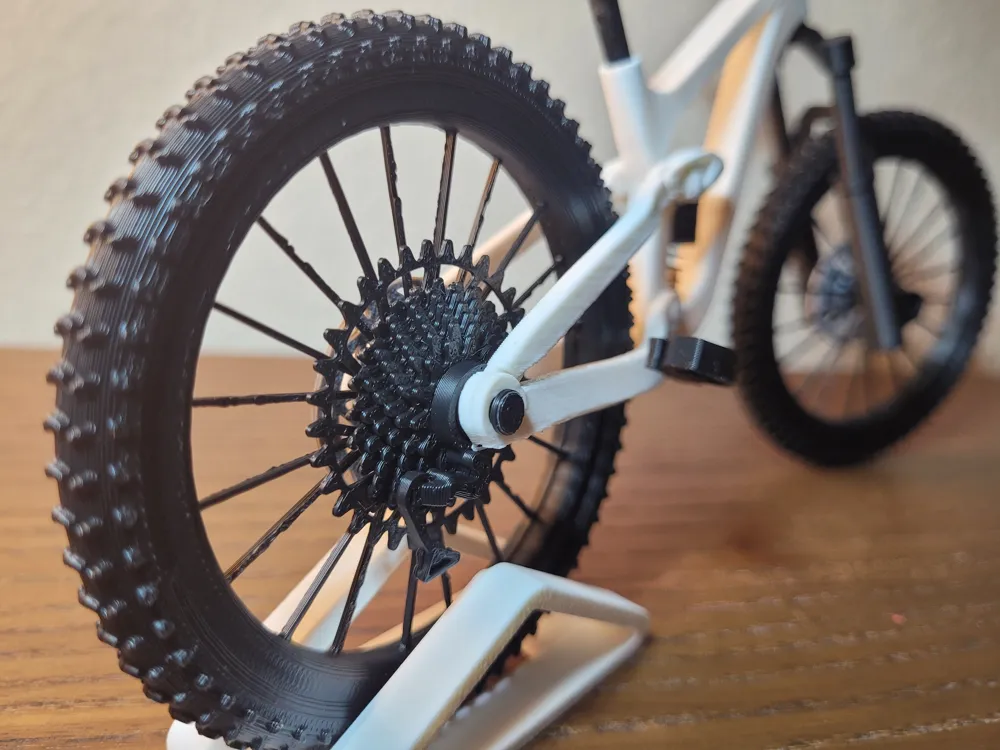
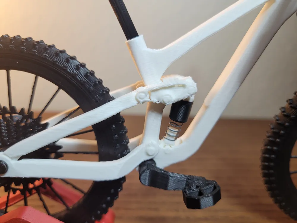
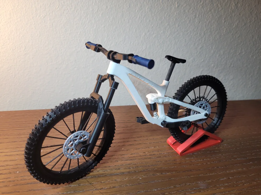
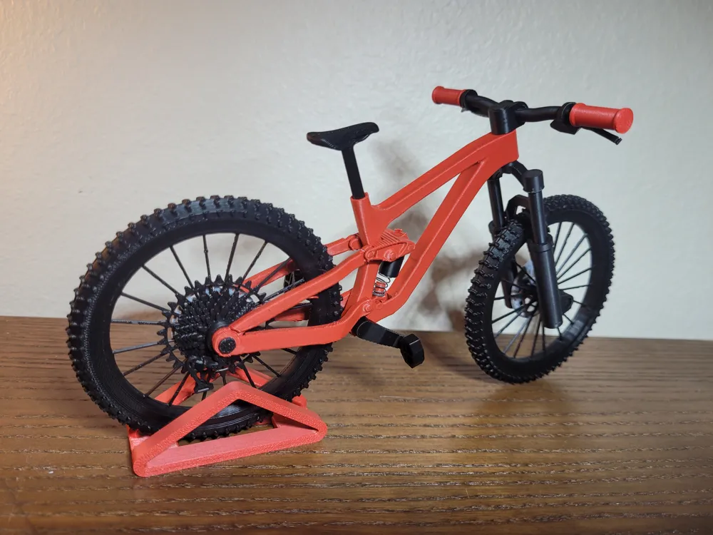
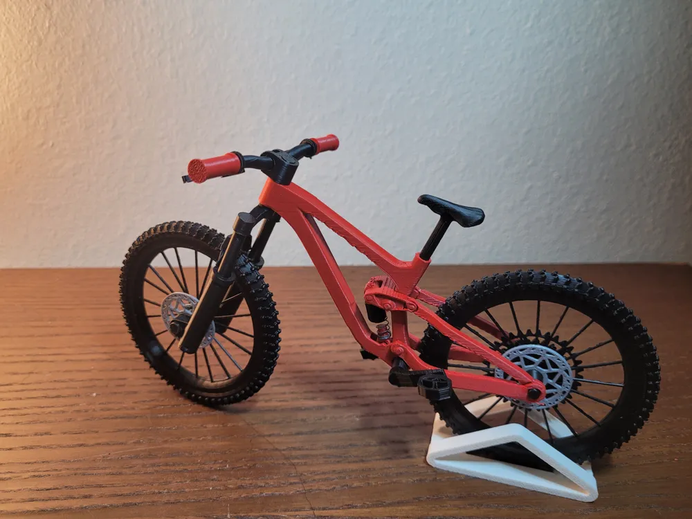

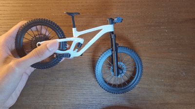
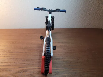
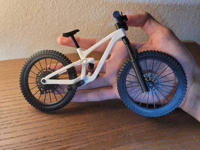
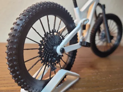
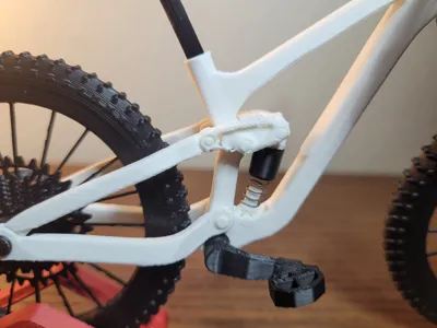
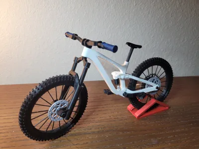
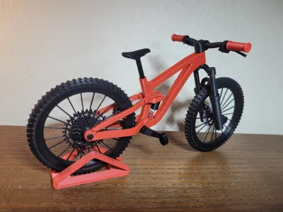
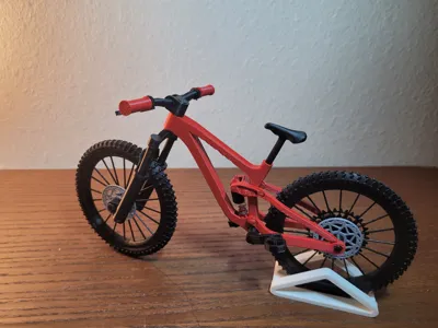
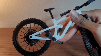
This is a 1:9 scale Full Suspension Enduro Mountain Bike model with working front suspension, rear suspension, rotating wheels and pedals. It is easy to print and assemble and has a lot of realistic visual detail. Fully 3D printed besides 2 spring (optional) for the suspension.
Based on a Trek Slash SE Gen 5!
For this model I tried to focus or realism as best as I could. All the bikes linkage is accurate to the real one - all freely moving and functional. also, accurate fork design and accurate scaling down of parts brings the whole build together!
Feedback is greatly appreciated!
You will need some glue!
CLEAN BUILD PLATE BEFORE PRINTING FOR BEST RESULTS!! :)
parts - especially on the frame have very tight tolerances!
Frame along with all the functioning linkage is fully print in place
Assembly is pretty easy! See steps below -
Both the front and rear suspension uses springs which you can easily find in pens.
Spring Dimensions -
Front Spring →
- Diameter - 5mm or less.
- Length - 40 mm or less
Rear Spring →
- OUTER diameter - 5mm or less.
- INNER diameter - 3.5mm or more.
- Length - Around 16mm or more (not a defined number - you can experiment!)
ASSEMBLY- (may seem long but don't worry - it's not really!)
Wheels ASSY -
-
- Place the wheel alignment guides (2 small blue pieces) into the grooves on one half of your wheel.
- apply glue all around wheel if needed.
- Find the 2nd half of the wheel using the text to match - then place the 2nd half of the wheel onto the first. Ensure proper alignment of the tire tread.
- Keep pressure on the wheel until glue sets - then set aside
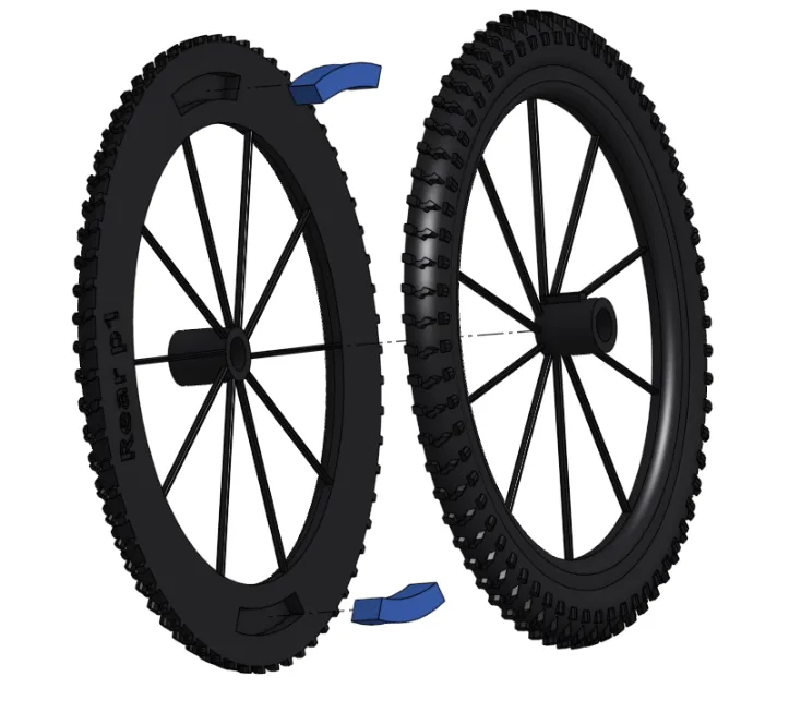
2. Repeat step 1 for 2nd wheel
3. On the wheel with the little keyhole on the hub (light blue thing) - slide on the gears - aligning the keyhole.
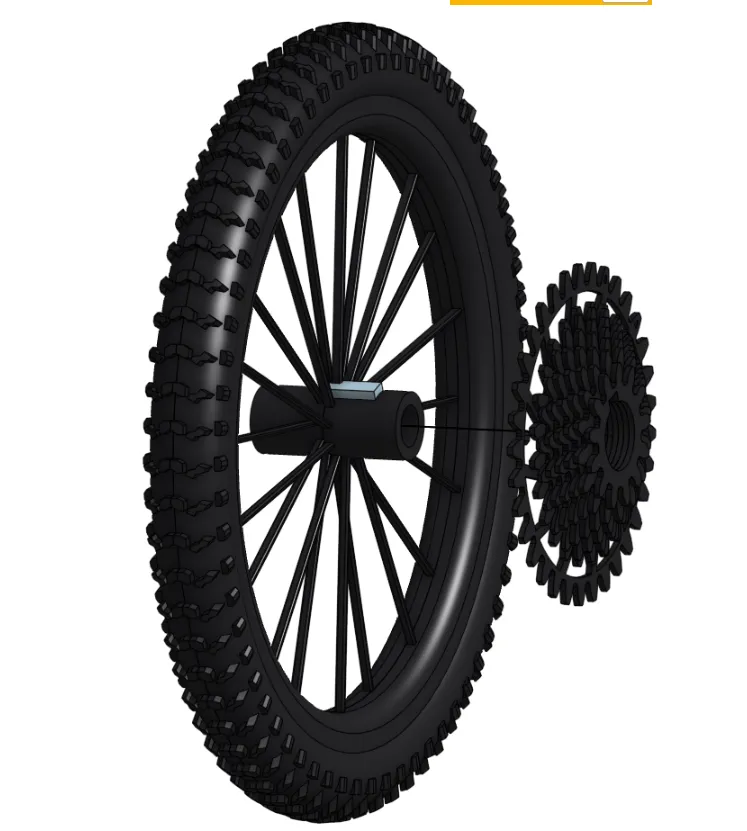
4. Slide on the derailleur - in front of the gears. (this is supposed to be loose)
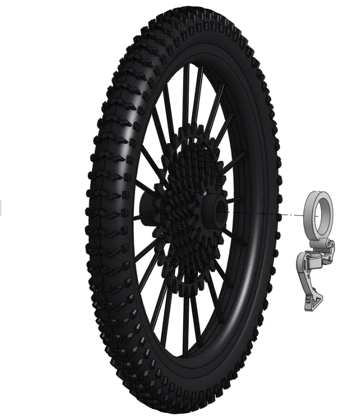
5. Turn the wheel over and slide on the brake disc. - set this rear wheel aside (apply glue if needed)
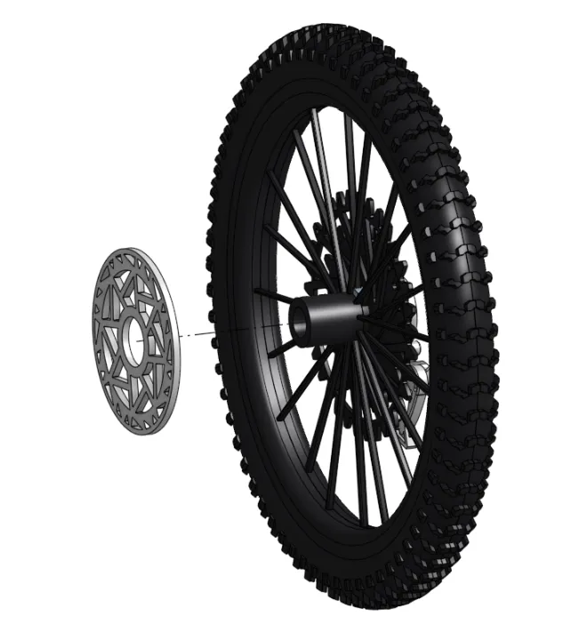
6. Slide the second brake disc onto the other wheel - set this front wheel aside
FORK ASSY -
1. Slide the fork stanchion into the fork body. ensure orientation is same as picture.
- (the circular side goes in first from the bottom of the fork body). (ensure that the stanchion has the little protrusions at the bottom - if it doesn't you're probably holding a wheel axle :) )
- Slide stanchions back and forth a few times to smoothen its motion.
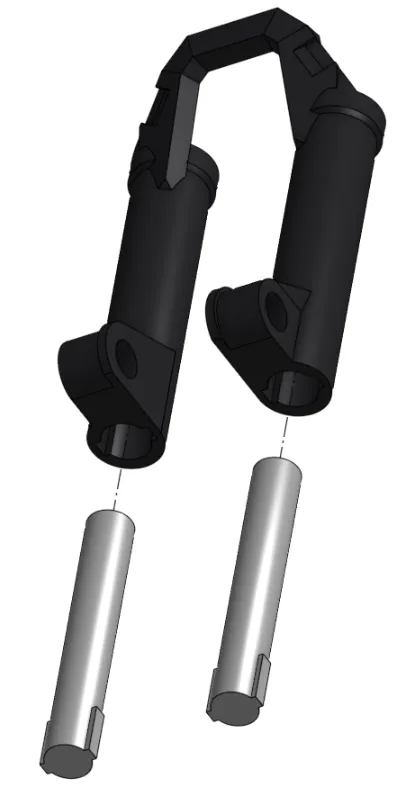
2. Press steerer tube into the stanchions. Apply glue to this joint if needed. (recommended)

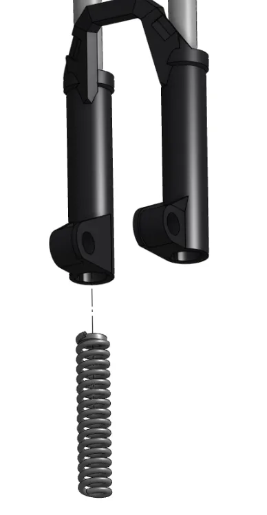
3. Slide the longer pen spring into any one of the bottom holes in the fork body.
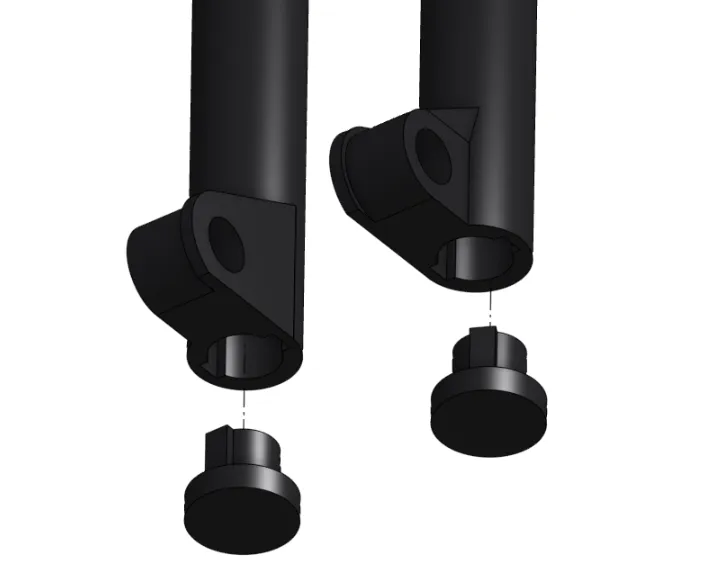
4. Press the fork body caps into the bottom of the fork body.
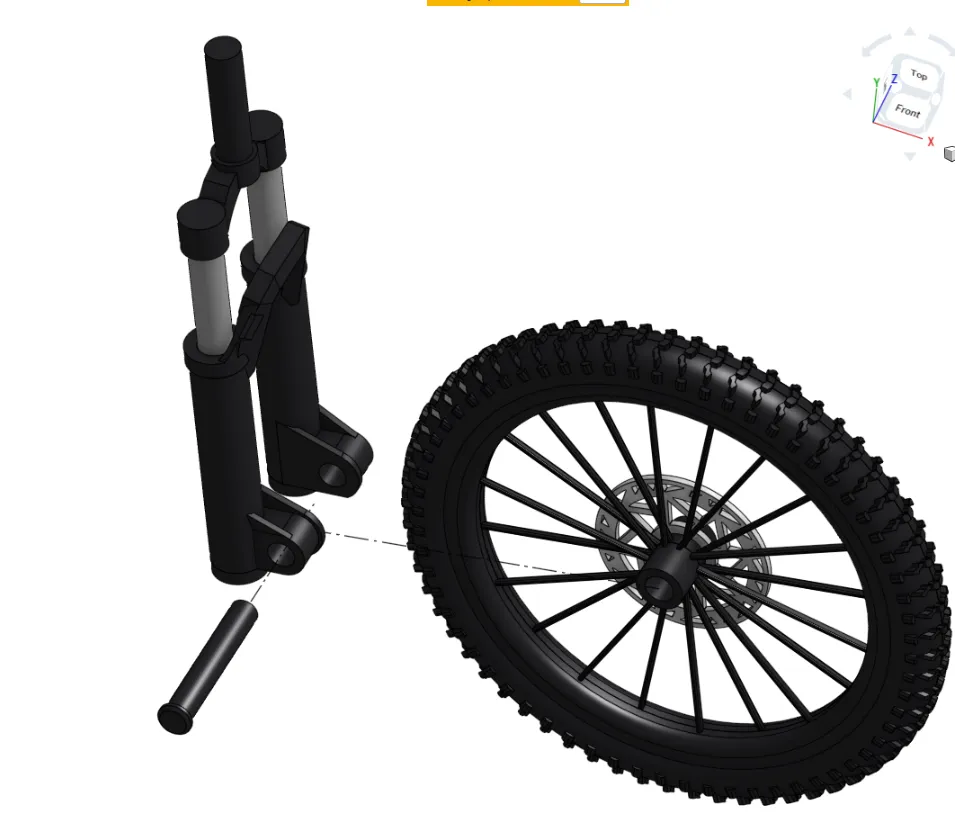
5. Slide your FRONT wheel in-between the fork bodies - secure wheel by sliding in front axle into place. (any one of the axles). then set aside
COCKPIT ASSY -
1. Slide stem through handlebar till it is in the center of the handlebar. (once centered apply glue to keep the stem in place)
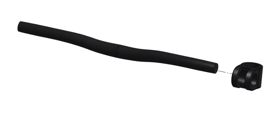
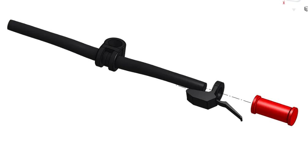
2. Slide on brakes - then grips. repeat on other side too (apply glue if needed)
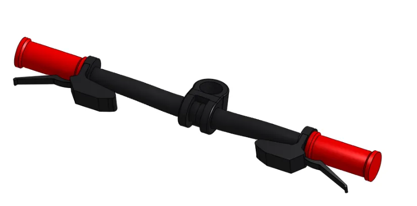
How it should look -
SEAT ASSY -
1. glue the two halves of the seat together. ensure it lines up properly!
MAIN ASSY -
PIVIOT ALL the linkage and joints on the frame gently by hand to loosen them up a little bit. the bottom rear suspension link may need a bit of force to loosen
1. Slide the whole front assembly we made earlier through the steerer tube on the main frame. - hold in place
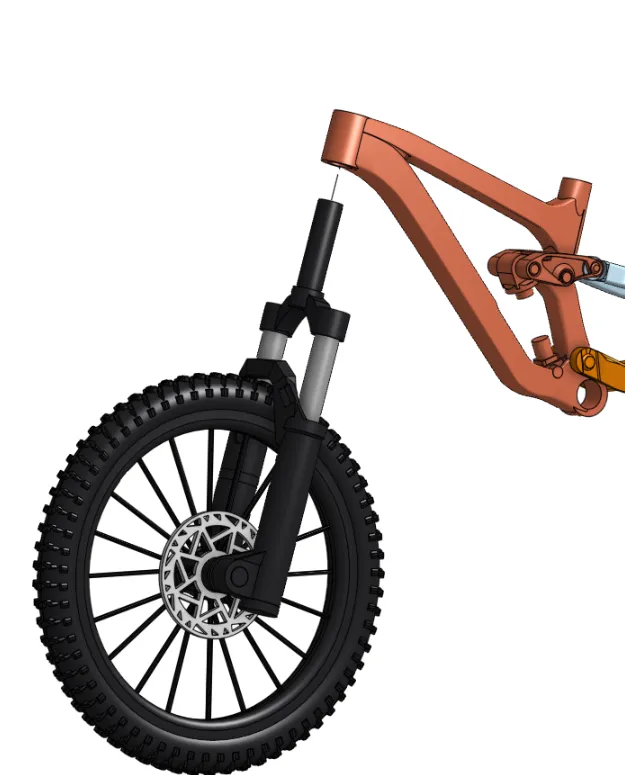
2. Press on the whole cockpit assembly onto the fork assembly to hold it in place. ( ensure your handlebars are straight - then Apply glue)
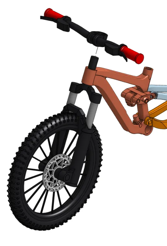
3. Press in bottom bracket onto the bottom of the main frame (may be hard to push in initially)
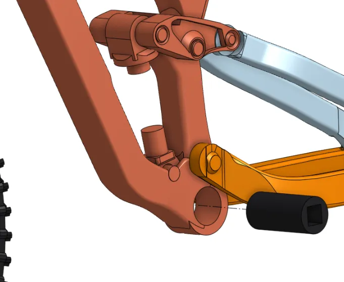
4. - press in pedals on either side. ensure opposite orientation. Twist on the pedals to loosen them - the flat part (where you place your feet) should spin independently .
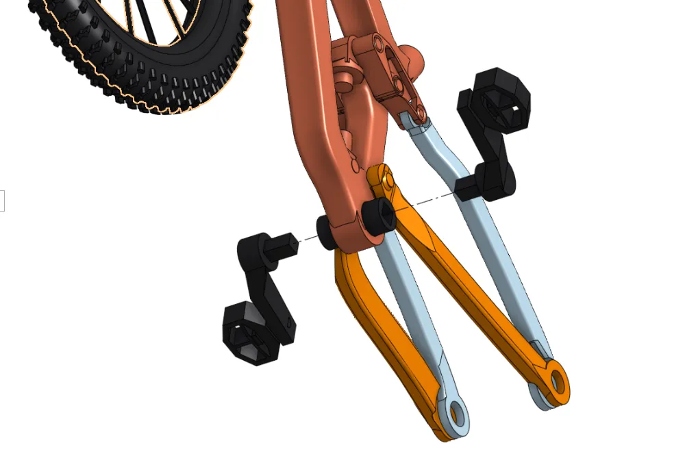
5. Slide the whole rear wheel into place and secure with the rear axle. It is very important to get the orientation of the swing arms right!
- first ensure that the blue and orange (see picture below) are completely separated and independent of each other. (remove residual supports or brims)
- Ensure the blue ones (in picture) are on the inside closest to the wheel and the orange ones (in picture) are on the outside - furthest from wheel
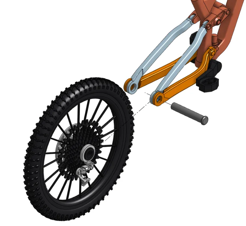
6. slide you second (cut to length) spring into the rear shock body (in this orientation) -
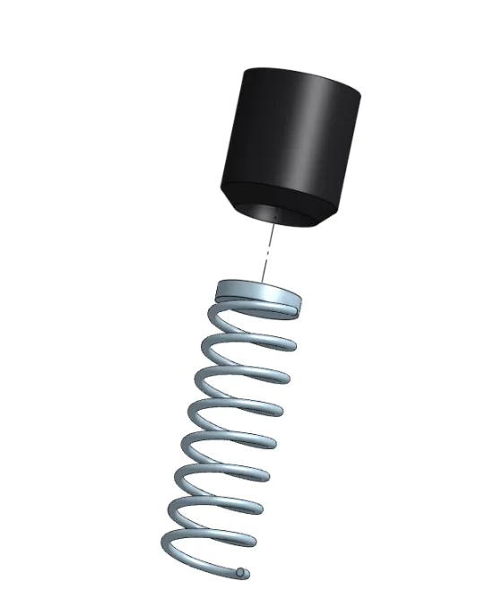
7. slide this into place on the frame (refer to picture below)
(this may be a little finicky)
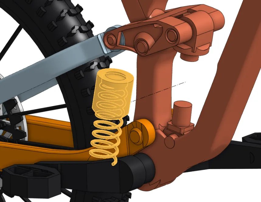
8. it should look something like this
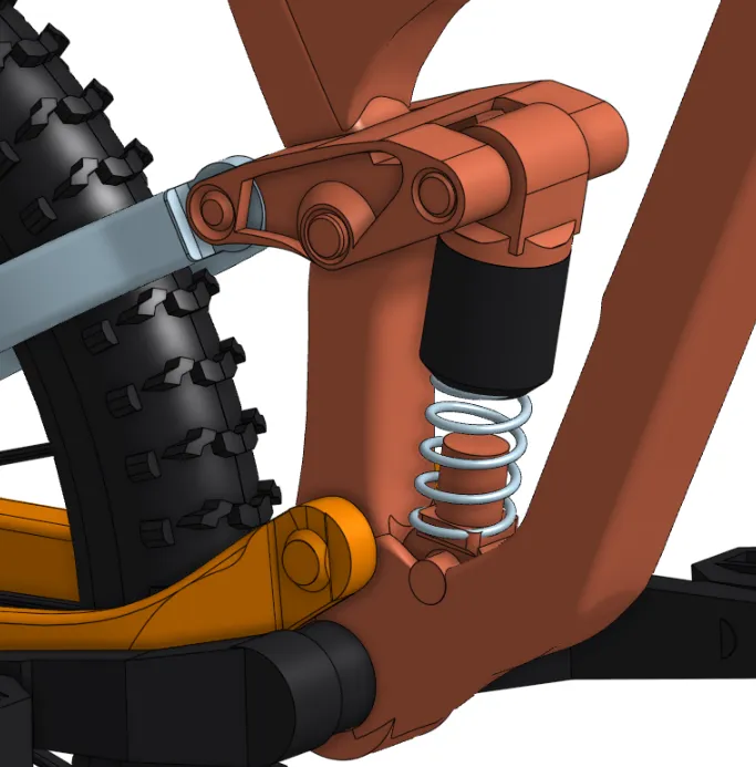
9. lastly - slide in the seat into the seat tube
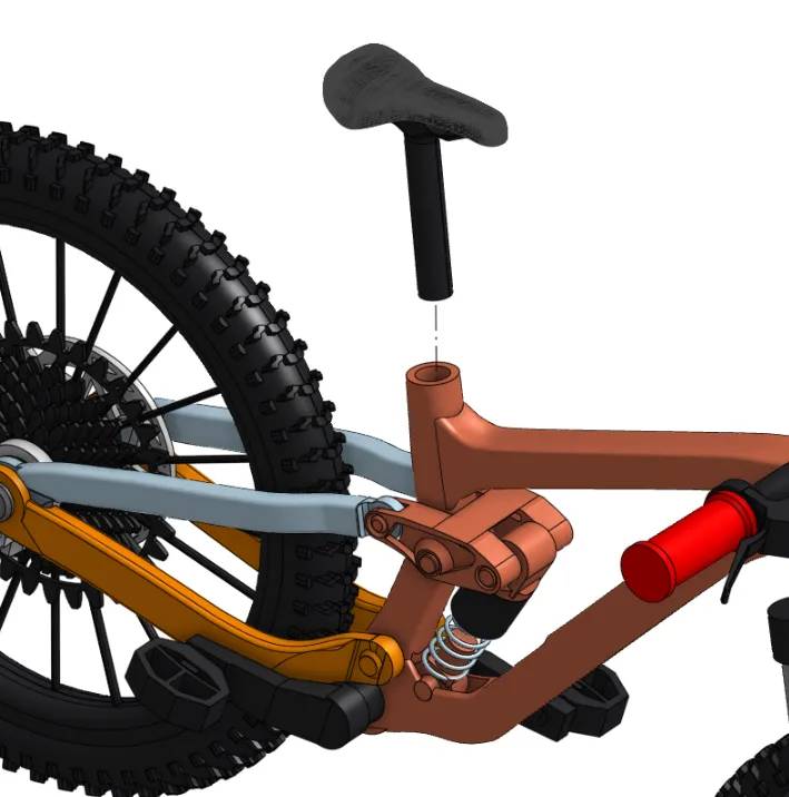
Enjoy :)
License

You shall not share, sub-license, sell, rent, host, transfer, or distribute in any way the digital or 3D printed versions of this object, nor any other derivative work of this object in its digital or physical format (including - but not limited to - remixes of this object, and hosting on other digital platforms). The objects may not be used without permission in any way whatsoever in which you charge money, or collect fees.


Comment & Rating (1161)