
Magnet Switch Lamp – Magnetic Toggle with Dimmer
Print Profile(3)


Bill of Materials





Description
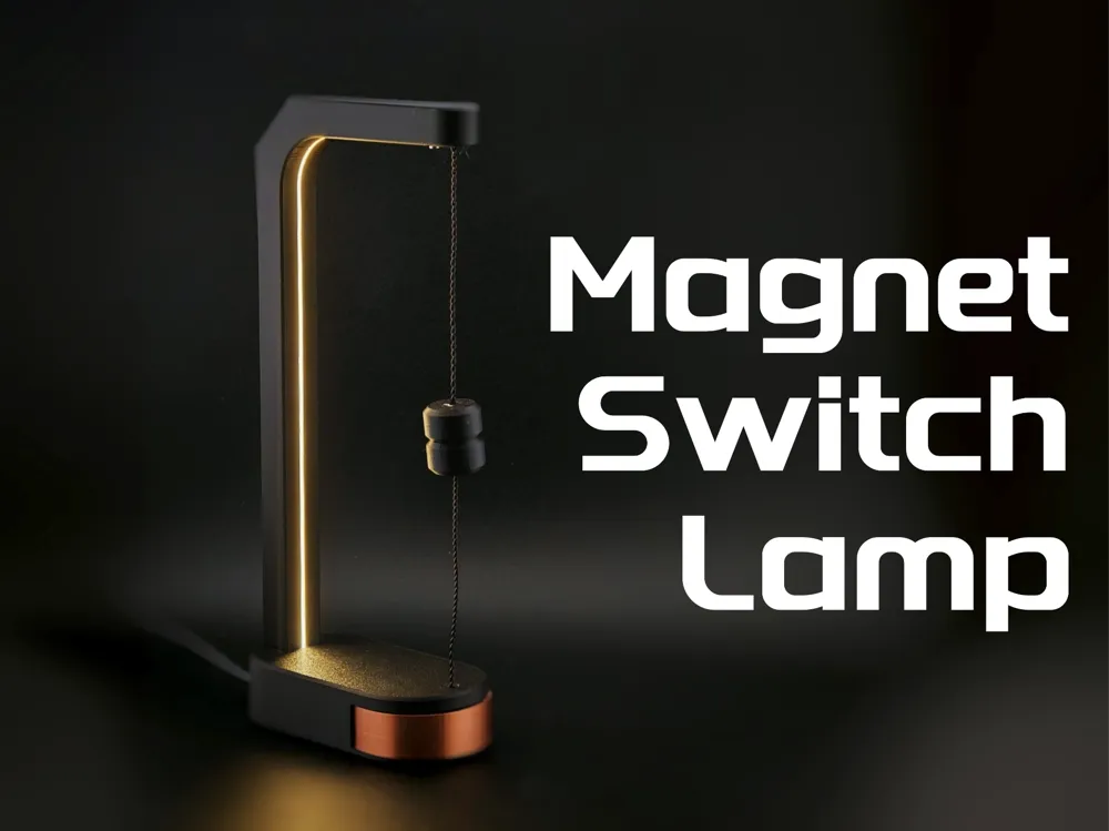
Magnet Switch Lamp
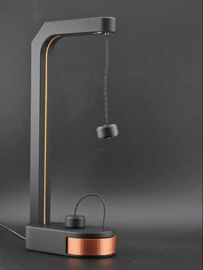
A minimalist lamp with a magnetic twist.

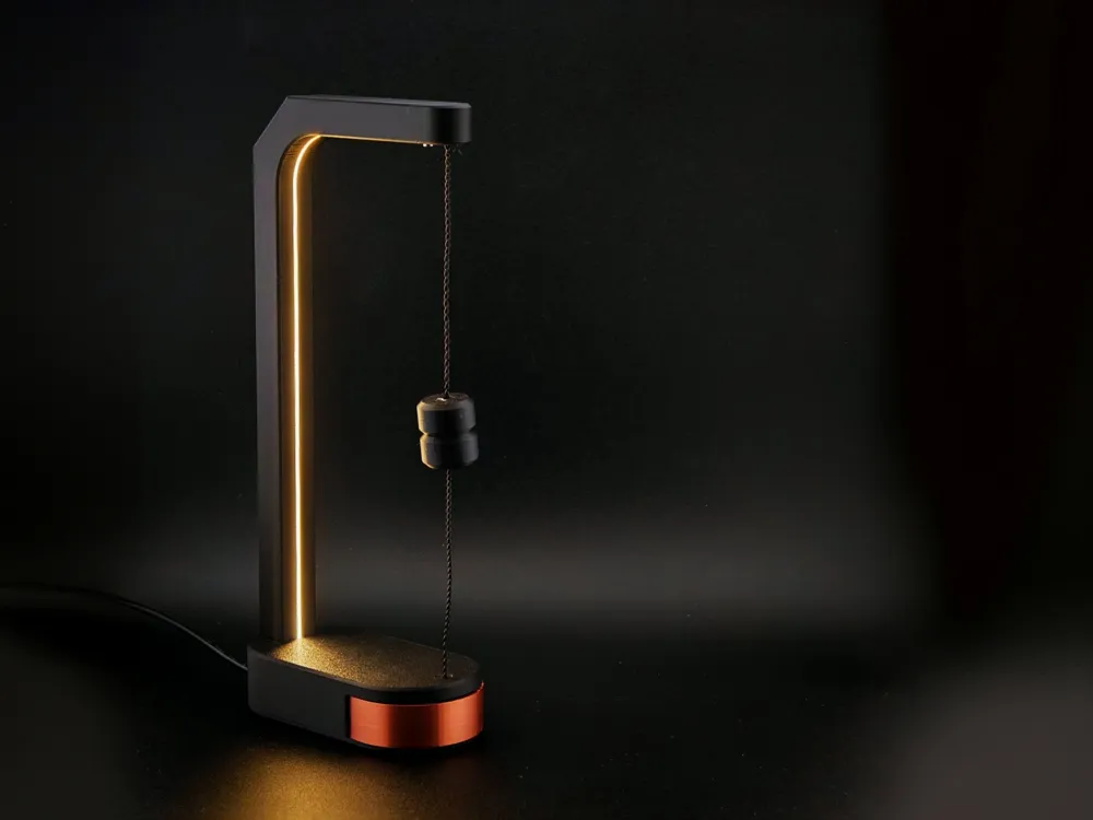
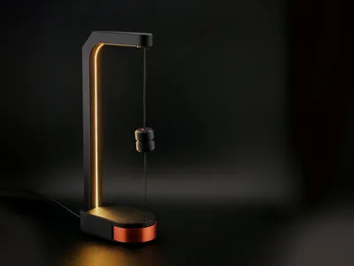
This clean, modern desk lamp turns on only when the two magnetic ends of the hanging cable connect creating a physical, satisfying switching action. Inside the base, the copper-colored dial isn't just a design accent: it's a smooth rotary dimmer that lets you adjust the light level with precision.
The warm light is provided by a COB LED strip embedded in the vertical arm, delivering even illumination without harsh shadows.
Key Features:
- Magnetic switch mechanism: the lamp only lights up when the magnetic ends are joined
- Integrated dimmer: control brightness via the copper front wheel
- Warm COB LED strip for soft, direct lighting
- Modern form with easy assembly and clean prints
- All components sourced from MakerWorld Maker Supplies
Assembly Guide
Required Parts (from Maker Supplies)
- M2×4 SHCS machine screw (10x)
- 300×1mm COB LED strip light (1x)
- 7mm round magnetic connector with SH1.0 (2x)
- Power distribution board (4-channel) (1x)
- Potentiometer board with SH1.0 connector (1x)
- 100mm wire pair with SH1.0 (5x)
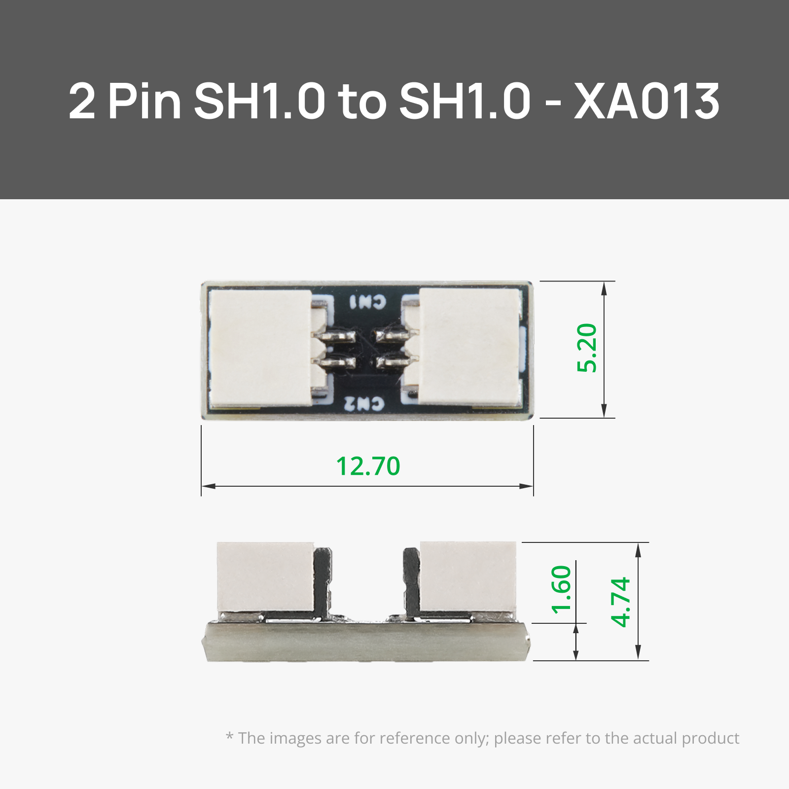
- SH1.0 to SH1.0 connector adapter board (1x)
Step 1: Test the electronics before assembly
To avoid reassembly later, connect all electronic components and verify functionality:
Wiring overview:
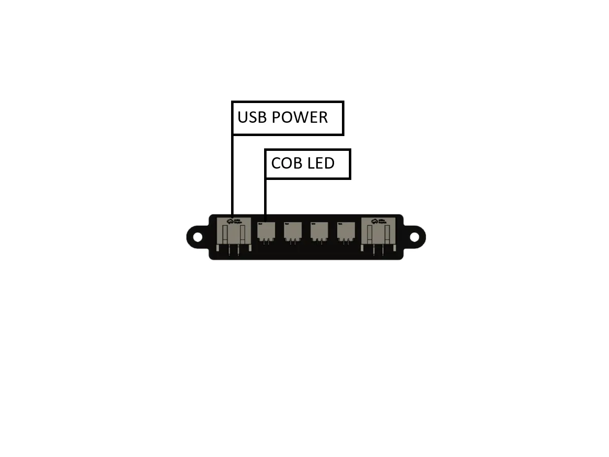
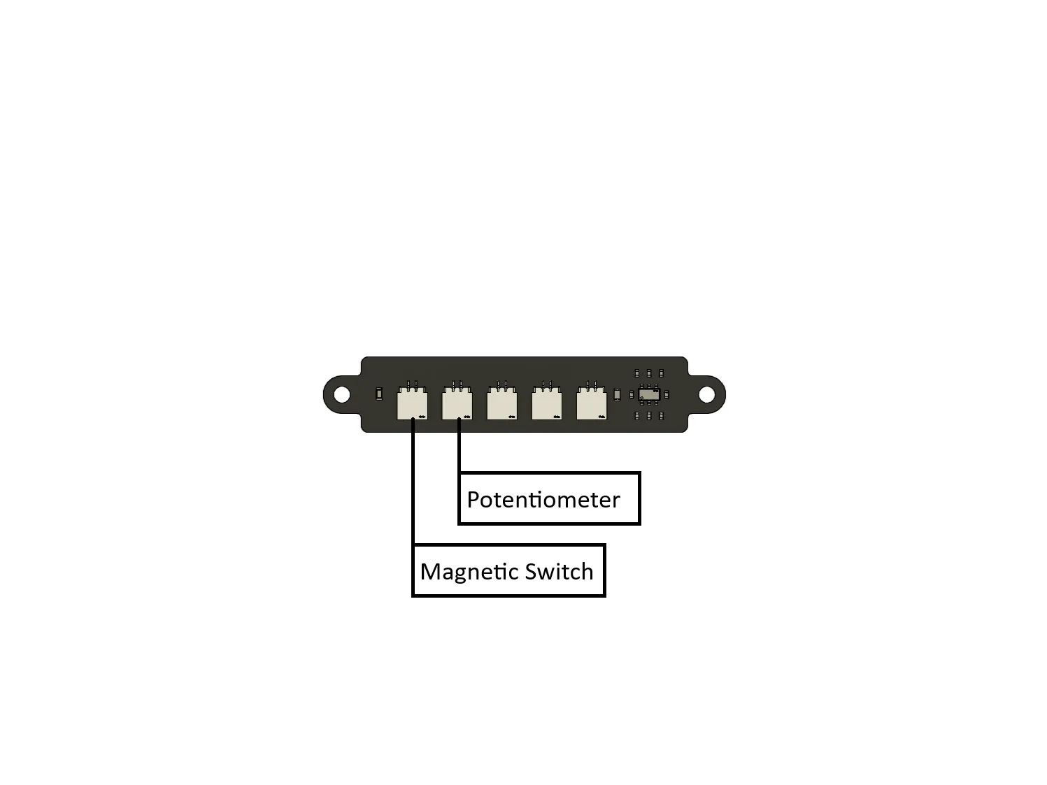
Refer to the diagrams provided:
- Side 1:
- Connect Potentiometer to the first port
- Connect Magnetic Switch to the second port
- Side 2:
- Connect COB LED to its port
- Connect USB power to the power input
Once connected:
- Plug in the USB power cable.
- With the magnetic switch disconnected, the light should remain off. Make sure to insert a jumper cable at the other magnetic switch
- Bring the magnet halves together — the light should turn on.
- Turn the copper-colored dial (rotary potentiometer) to verify smooth dimming.
Step 2: Mount Electronics and Route the Magnet Cable
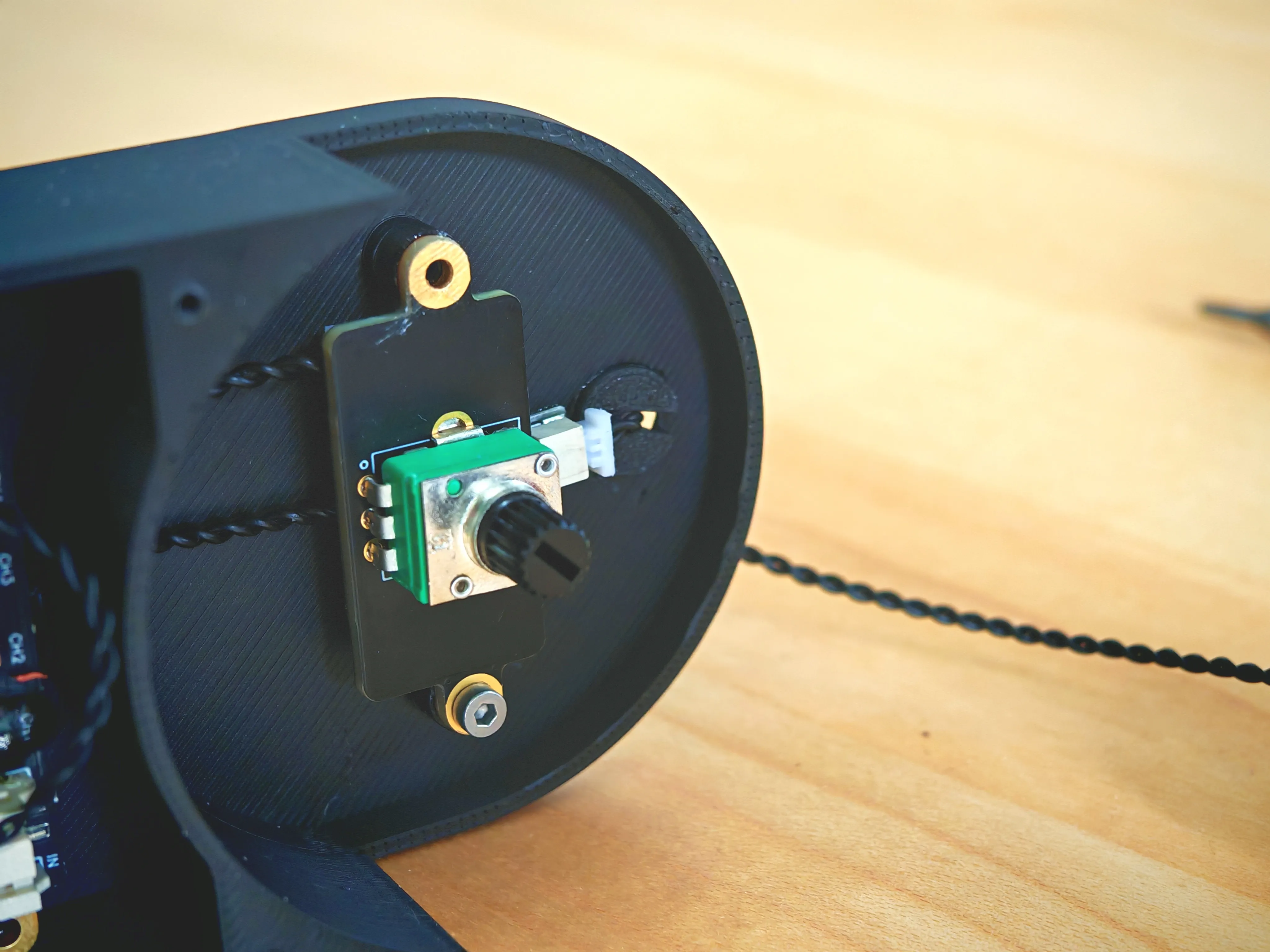
- Potentiometer & Front Dial:
- Mount the potentiometer board into its position behind the copper front dial.
- Secure it with two M2×4 screws through the mounting holes.
- Ensure the shaft aligns with the opening for the dimmer knob.
- If needed, trim or slightly sand the knob for a snug press-fit.
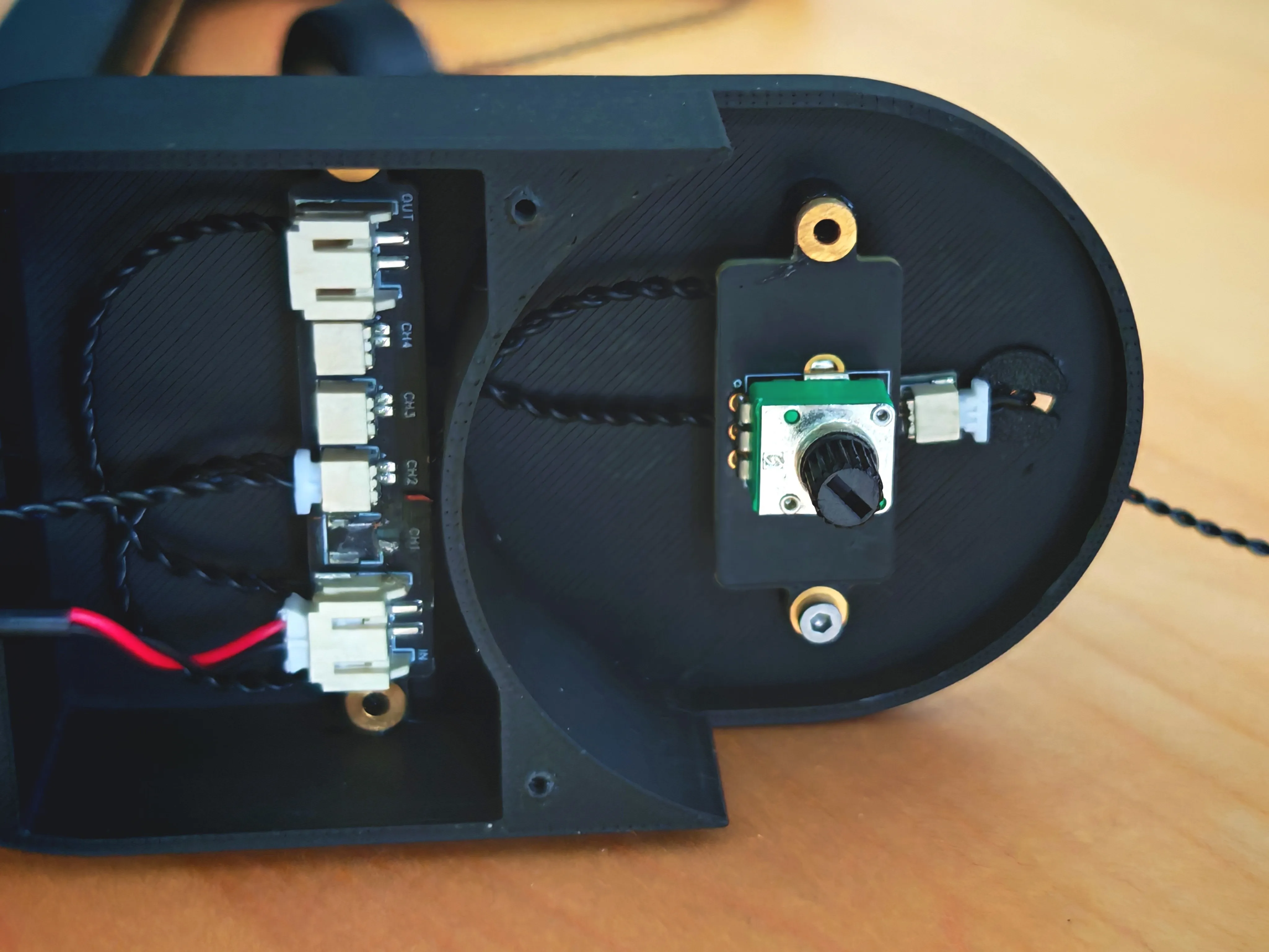
- Power Distribution Board:
- Place the 4-channel power distribution board into its cavity in the base.
- Fix it using screws and brass inserts if your model includes them.
- Connect the potentiometer using a SH1.0 cable to the right port of the input ports.
- Connector Adapter (SH1.0 Extension):
- If your cables are only 100 mm, use the SH1.0 to SH1.0 adapter board to bridge the connection.
- You can either:
- Glue the adapter board to the inside wall of the base (as shown), or
- Use a 200 mm cable instead, if available (more elegant, but depends on cost/availability).
- Magnetic Switch Cable:
- Route the cable for the magnetic connector through the small side hole in the base.
- Once threaded, glue the hole with the provided 3D printed cable collar for a clean exit and strain relief.
- Cable Management:
- Twist cables loosely to reduce clutter and avoid sharp bends.
- Keep wiring flat against internal walls to ensure the bottom cover closes cleanly.
tep 3: Install the COB LED Strip
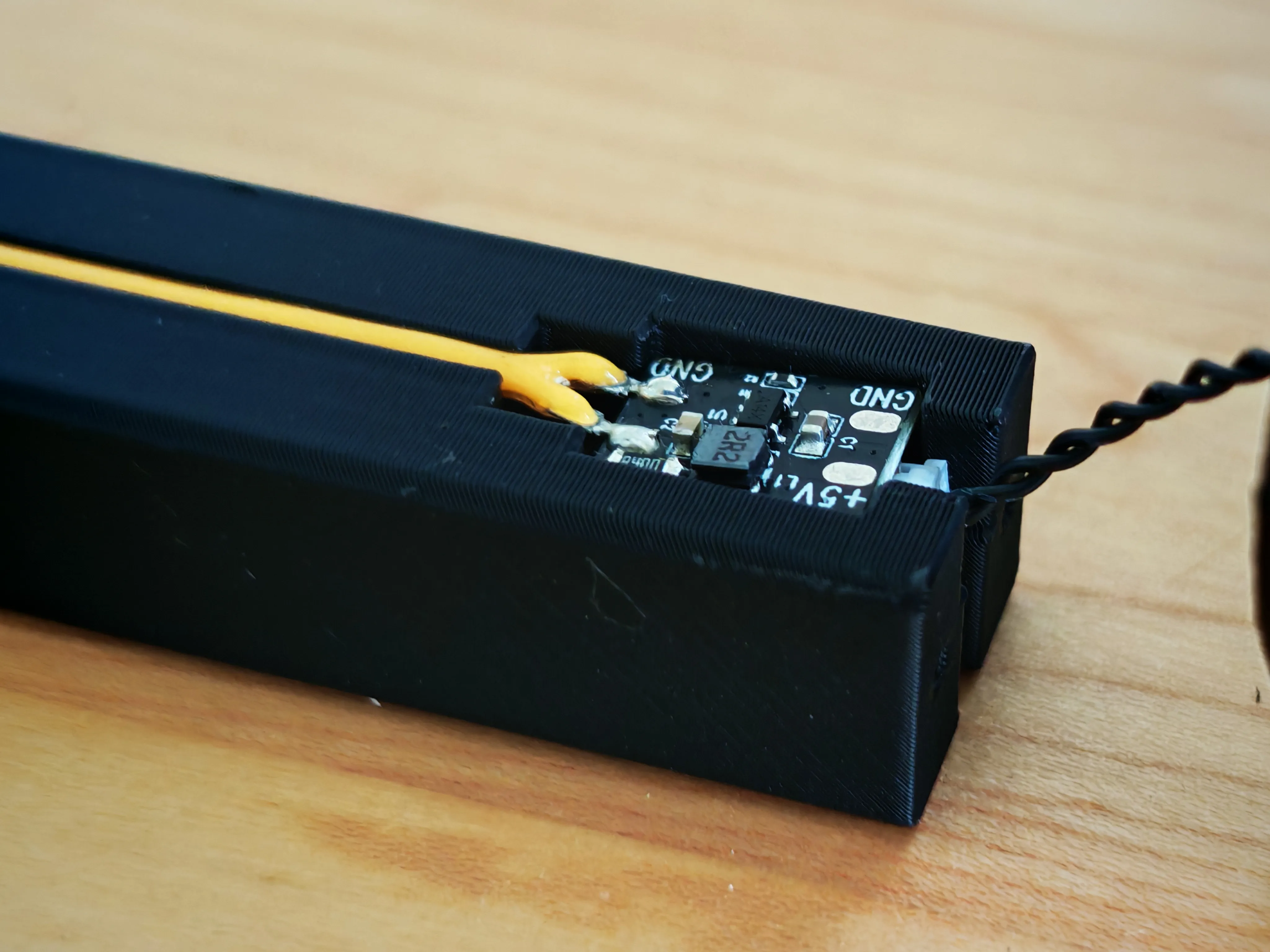
- Insert the COB strip:
- Carefully press the 300×1 mm COB LED strip into the vertical groove of the lamp arm.
- The strip should sit flush and straight. Avoid bending or twisting the LED strip.
- Route and connect the LED cable:
- Connect the LED wires to the controller board (as shown in the image).
- Secure the LED cable inside the LED housing using the provided recess or clamp feature.
- Connect to power distribution:
- Plug the LED connector from the controller board into the right of the output ports of the power distribution board.
Step 4: Assemble Top Housing and Magnetic Switch
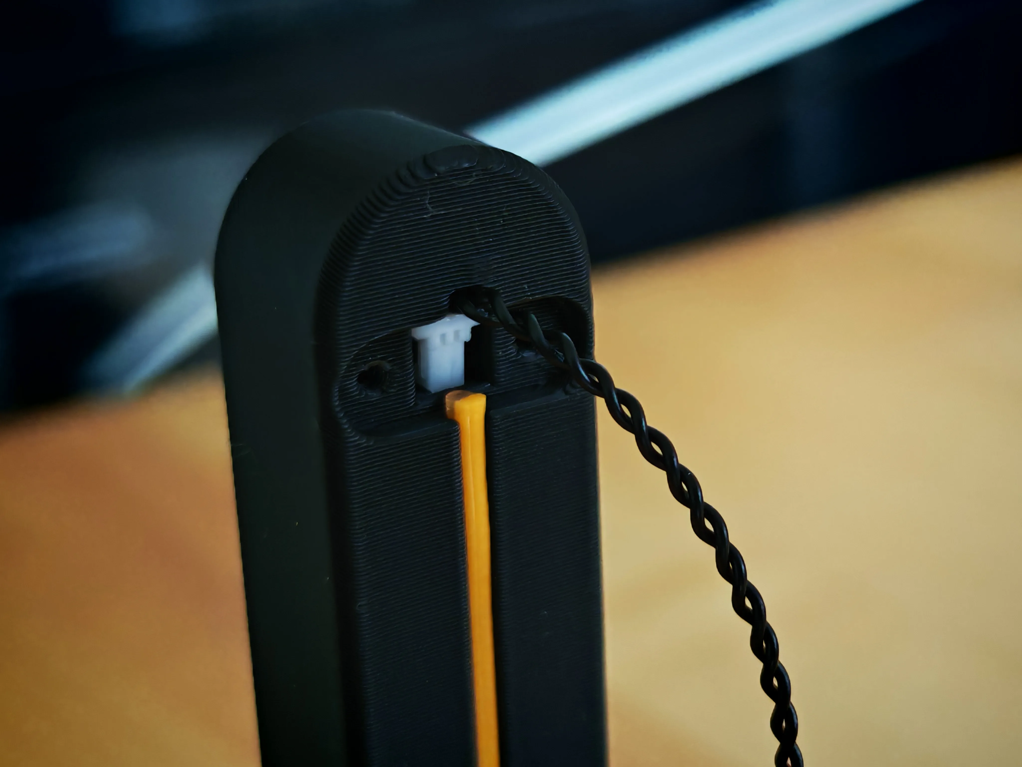
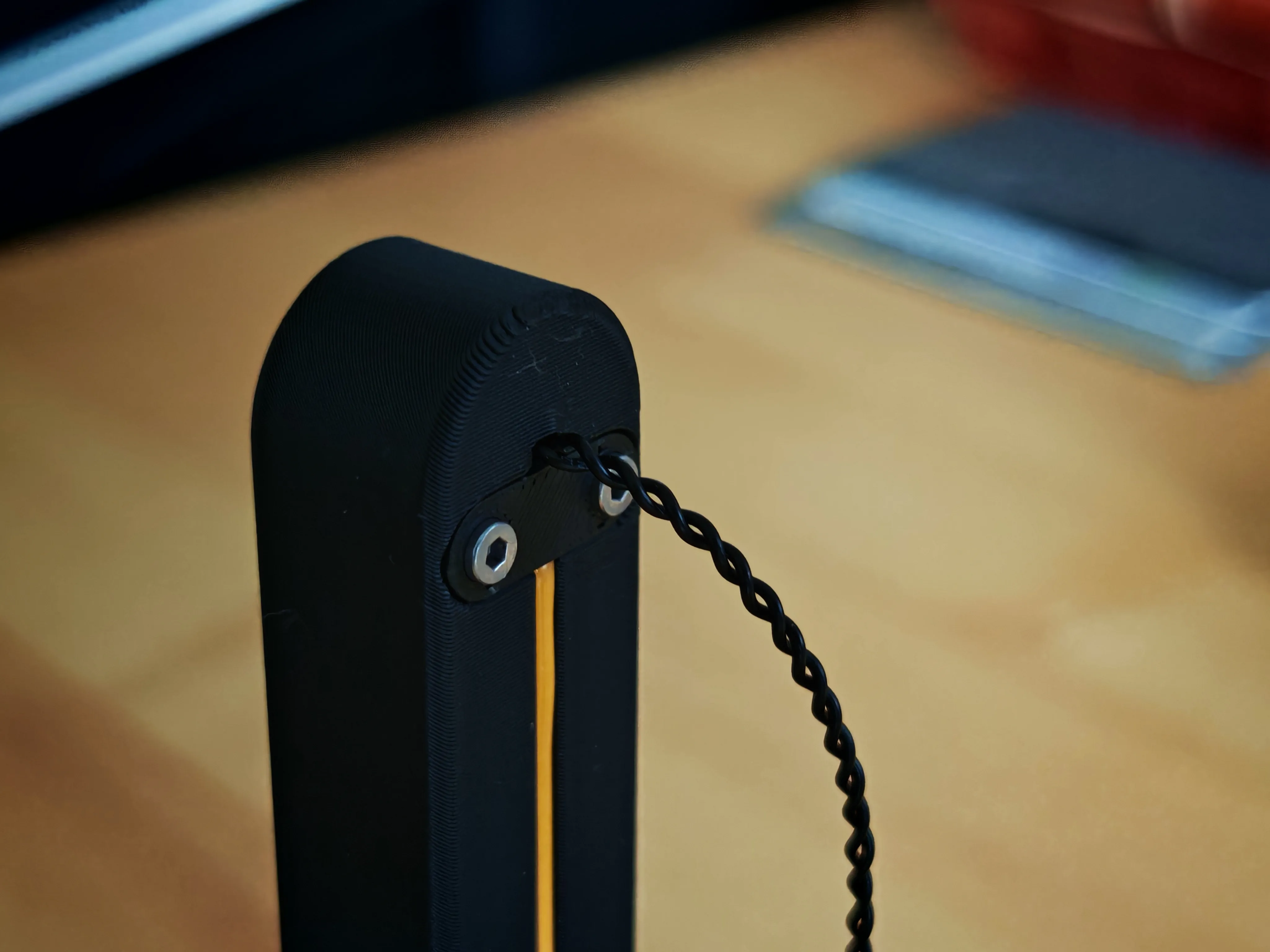
- Top cable feed:
- Insert one end of a 100 mm SH1.0 cable into the hole at the top of the lamp arm.
- Close off the top with the printed cable exit cover and secure it with two M2 screws.
- Magnet switch wiring:
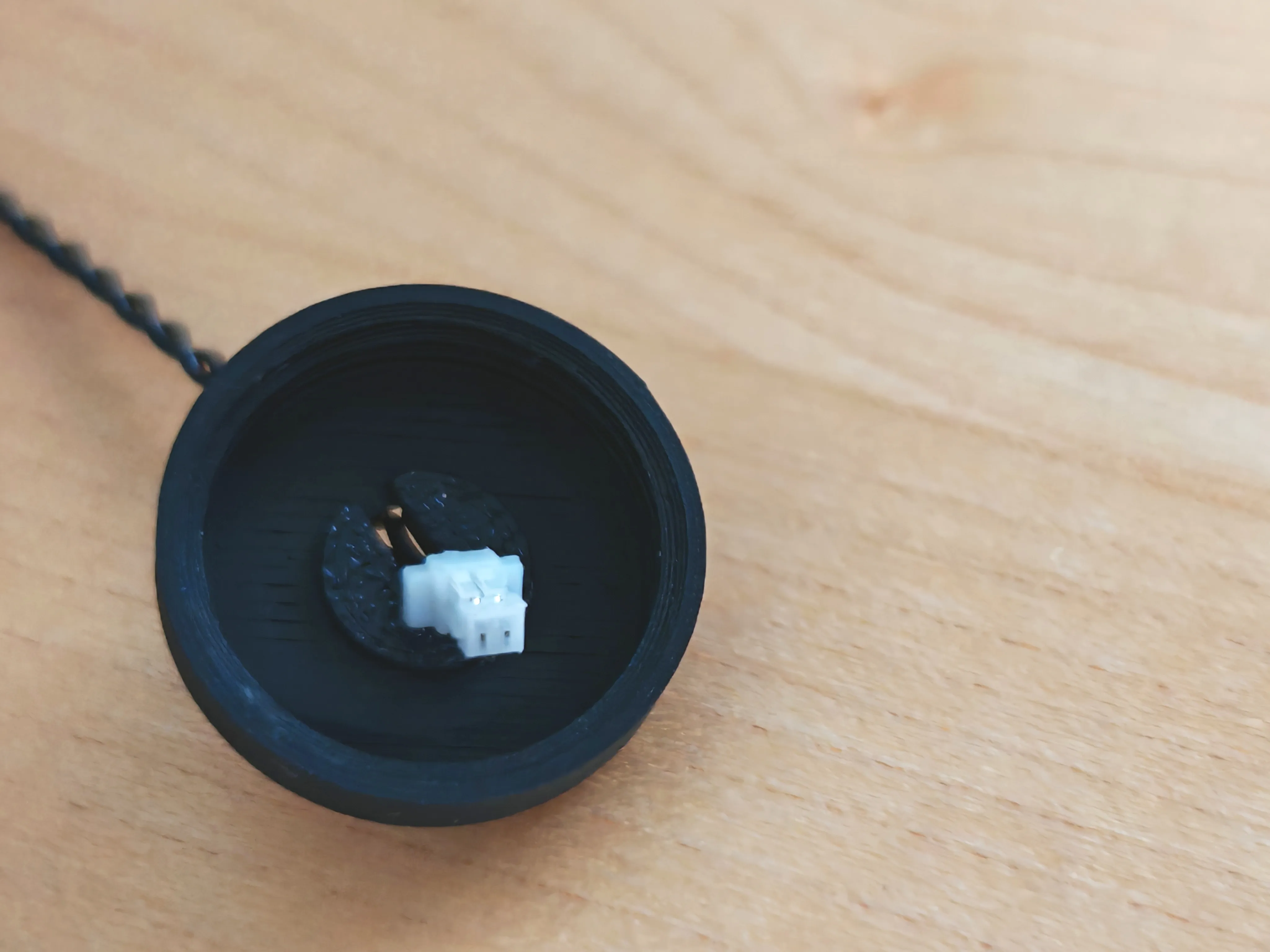
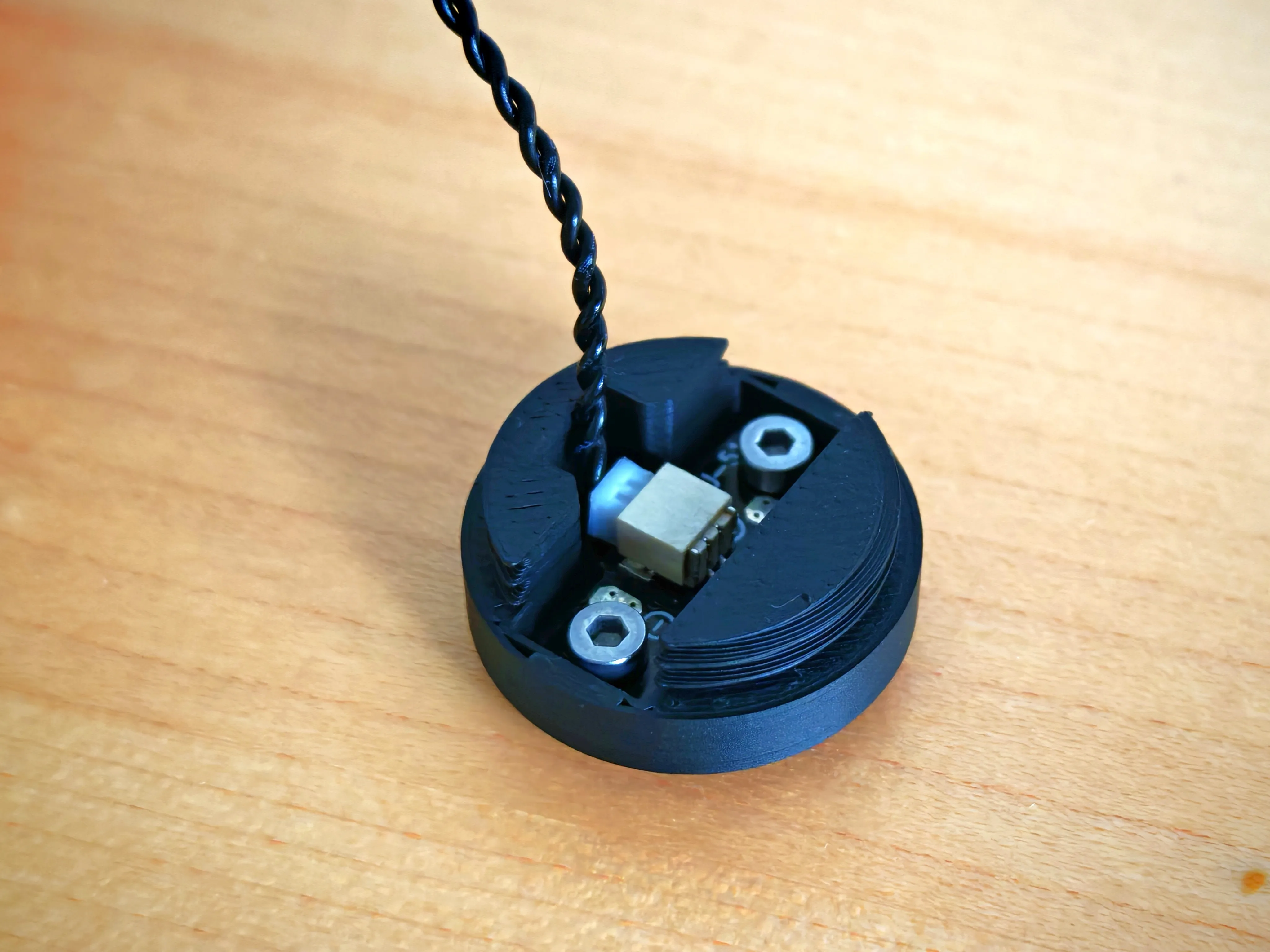
- Thread both cables (from the top and from the base) through the lower magnet half shell.
- Use the small 3D printed cable collar to hold the cables in place — glue if needed.
- Attach the magnetic switch board to the cables (polarity doesn't matter with most reed-based switches).
- Final magnet cover assembly:
- Secure the magnetic switch PCB into the upper magnet cover. The upper one needs to connected to a jumper cable
- Carefully screw both magnet halves together with M2 screws.
- The cable should remain gently twisted and untensioned between the upper and lower shell.
Step 5: Final Assembly – Closing the Lamp
- Secure the lamp arm:
- Insert the lamp arm into the base.
- Close the bottom cover:
- Carefully fit the bottom cover over the base, ensuring that no cables are in the way.
- Use M2×4 screws to fully close the lamp.
- Power it up:
- Plug in the USB power.
- Join the magnetic ends to turn on the light.
- Rotate the copper front dial to dim or brighten.
License

You shall not share, sub-license, sell, rent, host, transfer, or distribute in any way the digital or 3D printed versions of this object, nor any other derivative work of this object in its digital or physical format (including - but not limited to - remixes of this object, and hosting on other digital platforms). The objects may not be used without permission in any way whatsoever in which you charge money, or collect fees.


Comment & Rating (66)