ESP32 Remote PC Start LED + Photoresistor Trigger


Print Profile(2)


Bill of Materials

- Light sensor photoresistor GM5516 x 1: https://www.bastelgarage.ch/light-sensor-photoresistor-gm5516
- Yellow LED 5mm x 1: https://www.bastelgarage.ch/led-gelb-5mm
- ESP32 x 1: https://www.az-delivery.de/en/products/esp32-developmentboard
Description
This is a small ESP32 project box designed to allow remote power-on of a PC — by triggering the power switch pins using a light pulse.
I built this because my PC could not use Wake-on-LAN reliably after being disconnected from power — I wanted a solution that works as soon as the PC is plugged in, without requiring special BIOS settings or deep sleep. This way, as soon as the PC is connected to power, it can be started remotely via WiFi.
How it works:
- The ESP32 connects to WiFi and hosts a simple webserver (code below).
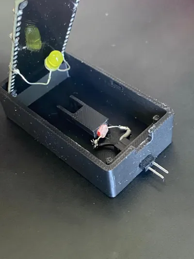
- When triggered, it lights an LED mounted inside the box.
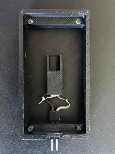
- Opposite the LED, through a small cylindrical hole, a photoresistor is positioned — connected to the PC’s start pins.
- The light pulse “bridges” the start pins — causing the PC to turn on (just like pressing the power button).
Usage:
You can call:
http://[ESP32-IP]/trigger?time=[duration in ms]
→ This turns the LED on for the specified duration.
In my setup:
- 1000 ms triggers PC startup or shutdown
- 5000 ms triggers a forced shutdown / kill
Box details:
- Custom-designed box holds:
- ESP32
- LED
- Photoresistor
- Lid is based on another model with small changes
- The rest was also inspired by that model but fully designed by me
- Designed for this ESP32 Version also usable for versions that are not as long (use Box with 2 pins)
Printing:
- Printed on Bambu Lab P1S
- PLA
- No supports required
- Printed flat
Disclaimer:
The box was designed with 4 pins to hold the ESP32 very tightly, but depending on your board tolerances they may not all fit perfectly. The 2 front pins alone are enough to securely hold the ESP32 in place — that’s how I use it myself.
Security note: This project uses a very basic webserver with no authentication. If you expose this to the open internet, it would be easily hackable. I strongly recommend using it only inside your own network, or protected via VPN or similar methods. Only use this if you understand the risks and know how to secure your network!
And please do a better job at soldering than me!
Code:
#include <WiFi.h>
#include <WebServer.h>
const char* ssid = "YOUR_WIFI_SSID";
const char* password = "YOUR_WIFI_PASSWORD";
const int ledPin = 32;
WebServer server(80);
void handleLightRequest() {
if (server.hasArg("time")) {
int ledOnTime = server.arg("time").toInt();
if (ledOnTime > 0 && ledOnTime <= 30000) {
digitalWrite(ledPin, HIGH);
server.send(200, "text/plain", "LED ON for " + String(ledOnTime) + " ms");
delay(ledOnTime);
digitalWrite(ledPin, LOW);
} else {
server.send(400, "text/plain", "Invalid time parameter");
}
} else {
server.send(400, "text/plain", "Missing 'time' parameter");
}
}
void setup() {
Serial.begin(115200);
pinMode(ledPin, OUTPUT);
digitalWrite(ledPin, LOW);
WiFi.begin(ssid, password);
while (WiFi.status() != WL_CONNECTED) {
delay(500);
}
server.on("/trigger", handleLightRequest);
server.begin();
}
void loop() {
server.handleClient();
}

Comment & Rating (0)