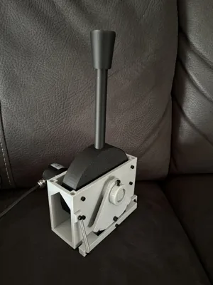
Throttle Lever (For Train Simulator)


Print Profile(1)

Description
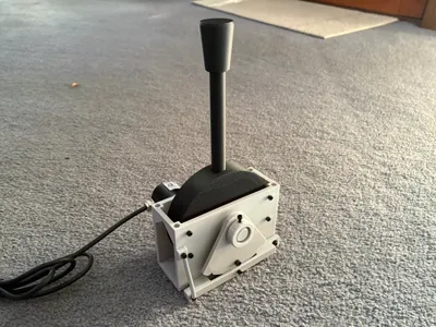
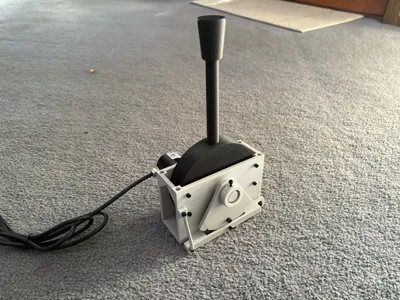
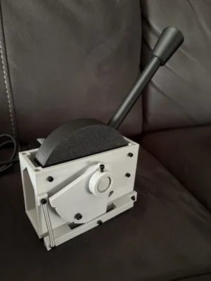
This is a throttle/ brake lever that can be used as a controller in games, specifically for Train Simulator Games.
This is the first model I have released to the public, if you want to support me please consider Boosting!
Boost Me (for free)
I am currently working on a revision of the main body. The main improvement/ change is a reduction in the amount of heated inserts required. The friction/ damping plate and top mounting heated inserts have been replaced with M3/M4 captive nuts, respectively. I am also making small tweaks as issues come up. All other previous parts will be fully compatible with the new body revision.
Also coming soon is an adapter for small, green, rectangular potentiometers (non-affilliate link) that works with the existing and new revision body file.
Update 13/10/2025: Added Notch Plate .STEP file so you can modify it to your liking.
The lever features a swappable notch plate, so you can change it out for different plates depending on the train you are driving (more notch plates coming soon).
It also has an adjustable pressure pad, allowing the friction of the lever movement to be changed.
Currently there is no solid code base, I have just been using an Arduino Leonardo acting as a USB joystick, and “Ts World Raildriver And Joystick Interface”. The code for the Leonardo can be found below, however you will need to tweak the values a bit as the min and max values are hard-coded at the moment.
Assembly
Parts Needed:
- One of each 3d printed part
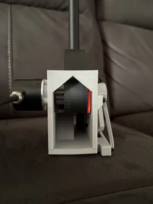
- High-resolution optical rotary encoder (600p/r is what I am using, however 200p/r or above is likely fine)
- M3 Heated Inserts x 10
- M3 bolts
- M3x4 x2 (For securing the spring)
- M3x8 x4 (You may be able to use M3x10s here if you don't have M3x8)
- M3x10 x7
- M3 Washer x2
- M4x30 bolt
- M5 Heated Inserts x 4
- M5 Bolts (For mounting the body to your panel)
- Hook Extension Spring (0.5x4.5x34mm)
- 9.5x4mm bearing, ID of about 3.5mm. I used some old precision bearings I had lying around (Barden SR2K25 C11)
Steps: (Images can be found in the Assembly Image PDF)
- Install all Heated Inserts in the holes of the body.
- 4 M5 heated inserts at the top
- 4 M3 heated inserts on the side opposite the encoder, in a rectangle pattern
- 2 M3 heated inserts on the Notch Arm
- 1 M3 Heated insert on the Spring Mount on the Body
- 2 M3 Heated insert on the embedded pin collars on the body
- 1 M3 Heated insert on the Disc Pin Collar
- Attach the rotary encoder to the side of the body using 3 M3x10 bolts.
- Push the Encoder Gear onto the pole of the encoder. (Note: ensure there is sufficient space between the gear and the body so it doesn't rub.)
- Position the Lever Disc and Pressure Pad in the body, and slide the Disc Pin through the body, Lever Disc and Pressure Pad.
- Ensure the Disc Pin is flush on the encoder side, there should be some sticking out on the other side.
- Secure the Disc Pin in place with an M3x10 bolt on the encoder side.
- Align the pressure pad and tighten it down using 4x M3x8 bolts.
- Install the Notch Roller into the Lever Arm by trapping it with an M3x10 bolt.
- Install the bearing into the Lever Arm, and bolt the lever arm to the body using 1 washer each side of the bearing.
- Install the spring, keeping it in place with 2 M3x4 bolts.
- Install the M4x30 bolt in the notch plate, and slide it over the protruding Disc Pin, locating the bolt into the hole in the Lever Disc,
- Secure in place with the Notch Plate Collar.
Documentation (2)
License
You shall not share, sub-license, sell, rent, host, transfer, or distribute in any way the digital or 3D printed versions of this object, nor any other derivative work of this object in its digital or physical format (including - but not limited to - remixes of this object, and hosting on other digital platforms). The objects may not be used without permission in any way whatsoever in which you charge money, or collect fees.
Comment & Rating (12)