DIY WiFi Smart Scale (ESP32/ESP8266 & HX711)


Print Profile(0)
Description
Description:
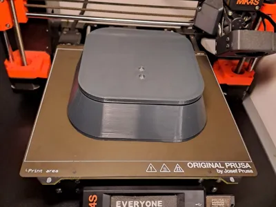
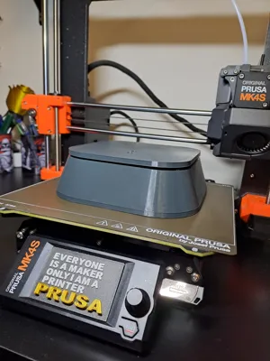
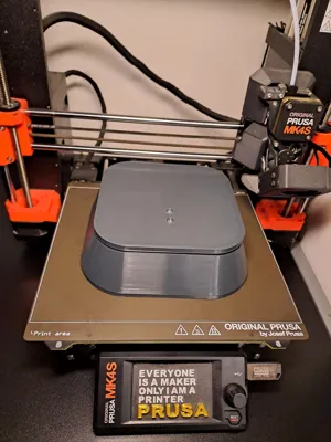
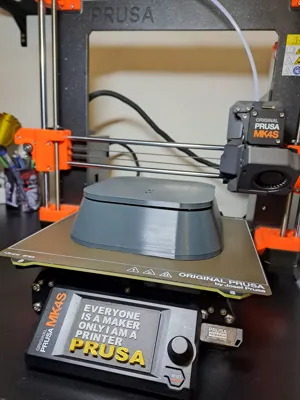
Build your own connected smart scale with this 3D printable enclosure! This design provides a robust and clean housing for the essential electronics, allowing you to create a WiFi-enabled scale that can send weight data to your desired platform.
Required Components & Hardware:
- 1x Load Cell Sensor: Designed for standard load cells with 4 mounting holes.
- Bottom Load Cell Mount: 2x M5x30mm screws with a low-profile, rounded head (similar to a Pan Head / DIN 7985 type). Tip: Pre-thread the printed holes with the screws for a perfect fit before final assembly.
- Top Load Cell Mount: 2x M4x30mm screws with a low-profile, rounded head (similar to a Pan Head / DIN 7985 type). Tip: Pre-thread the printed holes as well.
- 1x ESP32 or ESP8266 Development Board: The enclosure is compatible with common ESP boards.
- ESP Mounting: 2-4x M2x8mm Pan Head screws (DIN 7985 recommended). The design features four raised mounting points for the ESP board.
- 1x HX711 Load Cell Amplifier Module: This module amplifies and digitizes the load cell's signal.
- HX711 Mounting: 1x M3x8mm Pan Head screw (DIN 7985 recommended). There are two dedicated holes for this module.
- In-Print Nuts (Pause-at-Layer):
- 4x M2 Hex Nuts (DIN 934, approx. 1.6mm height) - For ESP board.
- 4x M3 Hex Nuts (DIN 934, approx. 2.4mm height) - For HX711 module.
- Note: These nuts are designed to be inserted into designated slots during the 3D printing process. Pause your print at the correct layer height to embed them.
Enclosure Features:
- Rear access port for Micro-USB connection to the ESP board.
- Precisely designed mounting points for quick and secure assembly.
Wiring Instructions:
- Load Cell to HX711:
- E+ (Load Cell) to VCC (HX711)
- E- (Load Cell) to GND (HX711)
- A+ (Load Cell) to A+ (HX711)
- A- (Load Cell) to A- (HX711)
- HX711 to ESP32/ESP8266:
- VCC (HX711) to 3.3V or 5V (ESP) – Check your HX711 module spec for power input, often 5V is fine.
- GND (HX711) to GND (ESP)
- DT (HX711) to a GPIO pin on ESP (e.g., GPIO D1 / Pin 5 on ESP8266 NodeMCU, or any suitable GPIO on ESP32)
- SCK (HX711) to another GPIO pin on ESP (e.g., GPIO D2 / Pin 4 on ESP8266 NodeMCU, or any suitable GPIO on ESP32)
- (Remember to define these pins correctly in your Arduino/ESP code.)
Software & Calibration:
You will need to write or adapt firmware for your ESP board (e.g., using Arduino IDE) to read data from the HX711, perform calibration, and send data via WiFi. Many libraries are available for the HX711.
Get started and create your own smart weighing solution!
Print Settings
Printer brand:
Prusa
Printer:
i3 MK4S
Rafts:
No
Supports:
Yes
Resolution:
0,2 Structural (Input Shaper)
Infill:
25%
Filament material:
PETG
Filament brand:
Prusa
Filament color:
Anthracite Grey
Comment & Rating (0)