
Wind Turbine V140cm
Print Profile(1)

Description
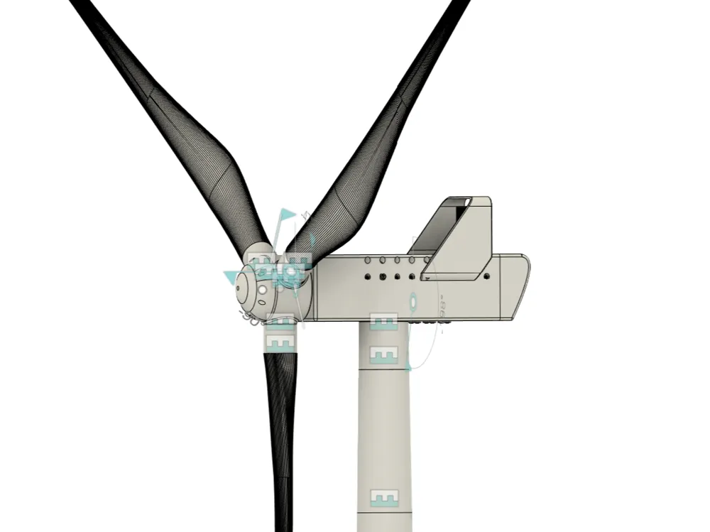
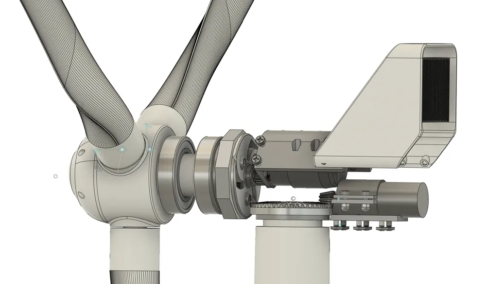
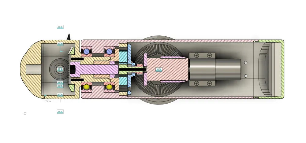
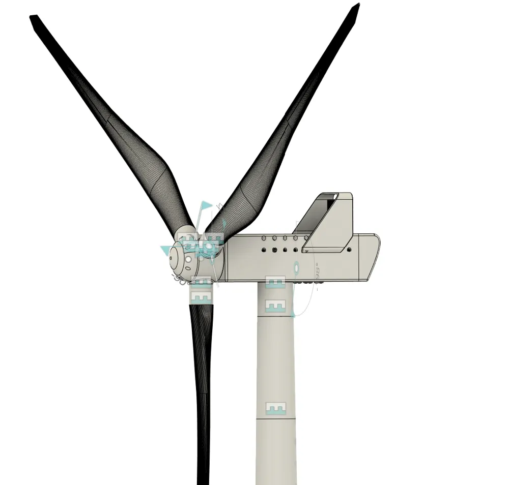
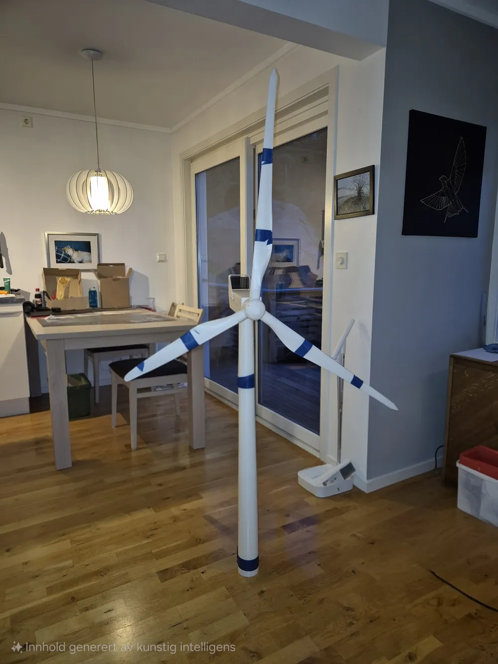
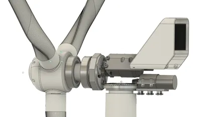
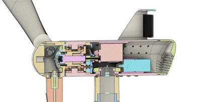
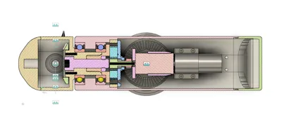
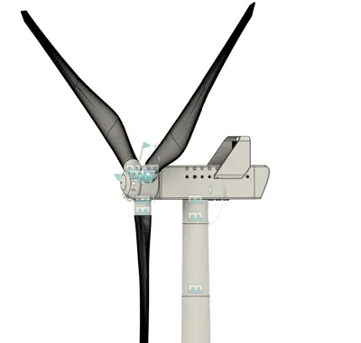
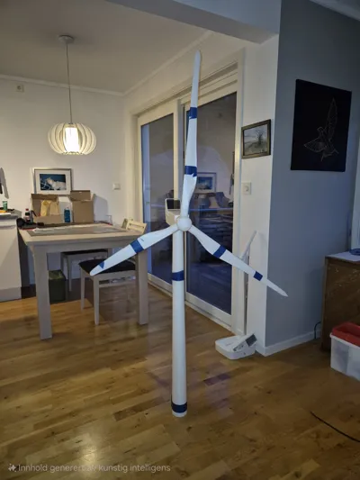
Fully functional model of a wind turbine. 140cm diameter, 175cm tall. Need 36mm electric motor for generator, and a JGA25-370 Geared motor for yaw control. Wings, tower and other parts may need to be glued.
Also need:
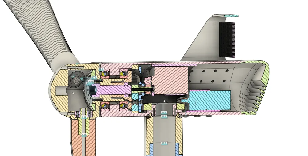
- Ball bearings:
- 6006 x2 for hub
- 6000 x3 for wings
- 4*8*3 x4 for gearbox
- 6*13*5 x1 for gearbox
- 5mm balls x20 for custom yaw bearing
- 3 and 4 mm nuts and bolts
- M12x45mm hex socket bolt
- M12 nut
- M4 or M5 threaded rod and counter sunk barrel nut for connecting the wings (4 x 12mm Slotted Raised Countersunk Barrel Nut, A1 Stainless)
The threaded rod is required to assemble the rotor. It should be inserted into the inner part of the wing with a double nut (to prevent the nut from shifting during assembly and operation), then passed through the hexagonal connection piece, the pitch bearing (metal bearings type 6000 should be used instead of the supplied plastic bearings), and finally secured through the pitch gear using the countersunk barrel nut.
The 2.5 mm rods supplied with the wings are best replaced with 2.5 mm carbon rods. Additionally, a 5 mm carbon or aluminium tube should be inserted and glued into the inner part of the wing for added strength and safety. This tube can be glued together with the hexagonal connection piece used to align the pitch gears, further reinforcing the joint between the wing and the hub.
It is advised to assemble the rotor using only the inner wing segments for all three blades first, ensuring proper pitch functionality and a good fit. Adjust the threaded rod length to achieve correct assembly of the wing–hub joint before gluing the two outer wing segments in place.
The Threaded connection pieces on the top of the tower is advised to print in stonger materials than PLA, as the forced acting on the naselle/tower joint is large under normal opperation. A material like PCTG or nylon (PA6 or PA12, perhaps with fiber reinforcement) with perfect layer adhesion is adviced.
Good luck in assembly and further development of electronics for automatic yaw controll.
(Some issues have been observed when the rotor speeds up. The pitch has been slightly altered by aerodynamic forces due to insufficient friction in the pitch mechanism, causing the turbine to lose efficiency and slow down. This effect helps prevent rotor runaway in strong winds, but an additional component for the hub is being planned to eliminate this behaviour.)
License



Comment & Rating (14)