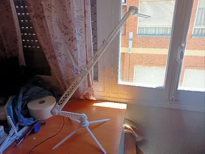
Arm for Illumination - Brazo para Iluminar V2


Print Profile(3)


Description
IMPORTANT
This model is a second version of a model that I removed from the publications due to certain issues that I have improved. I have also removed some non-functional elements.
I have also shared the STEP files of the model for responsible use.
Materials:
- 6 M3x20mm (25mm optional) screws/nuts (for the large arm).
- 4 M3x20mm screws (for the base).
- 4 M3x20mm screws/nuts (for the arm shafts).
- 1 M3x20mm screw/nut (for the 360° shaft).
- Phillips head screwdriver.
- Pliers + extra disposable screw.
Note: The nuts should have a 5.5mm flat side-to-side external measurement. They are press-fit.
Recommendation:
- Print with PETG.
- 3 walls.
- Supports on some parts.
- Minimum infill.
- Place a rubber or stiff cardboard between the shafts and the ball joints to increase friction.
ASSEMBLY
1) Insert an M3x20mm screw into the part that will serve as a 360° shaft for the entire arm.
It must be fully inserted.

2) Embed a nut in the base of the legs.
Use the disposable screw and pliers to help.

3) Attach the 4 legs. No nut is required.
Just screw.

4) Embed a nut in the 360° shaft.
Use the disposable screw and pliers to help.

5) Attach the part from step one and the 360° shaft in the middle, with the base at the bottom.

6) To save time, embed the nuts into all the printed nut recesses.
Use the disposable screw and pliers to help.
Then insert the M3x20 screws through these nuts into the flat side.
IMPORTANT: There is only one of the larger nut and three of the smaller ones.

7) Attach the first arm to the ball joint of the shaft.


8) On arm 2, embed a nut on the back side of the two parts with shafts.


9) Connect the previously mentioned parts with screws using the 6 M3x20mm screws/nuts.
First insert the nuts through the cavity and then pass the screw, without tightening too much to avoid breaking the part.
IMPORTANT. I MADE THE MISTAKE OF PRINTING THE PARTS WITHOUT MODIFYING THEIR OWN ANCHORAGE
BUT YOU HAVE THE FINAL AND FUNCTIONAL VERSION.


10) Place the nut between arm 1 and arm 2.

11) Embed a nut in the ball joint of the third arm.

12) Connect arm 2 and the ball joint with a nut.

13) Attach the third arm to the shaft of the ball joint and a nut.

14) Done! You're finished.
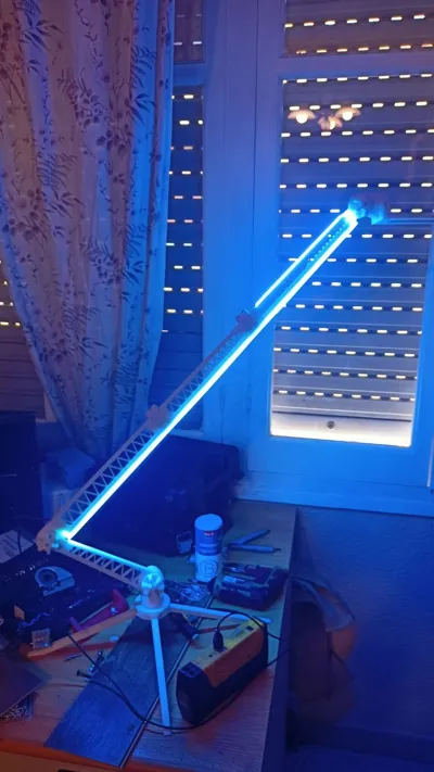
MOD LED lights in the body
9.5) There are 3 parts with space for LED strips up to 6mm wide. They are placed in
the lower part of the arm. This has a small space to pass the cables to the back.
It is screwed in with the same screws and double-sided tape or silicone can be used to adhere it in the more distant areas.


MOD for anchoring to tables.
14.5) This mod allows you to place it on table edges. It's an extra.


License
You shall not share, sub-license, sell, rent, host, transfer, or distribute in any way the digital or 3D printed versions of this object, nor any other derivative work of this object in its digital or physical format (including - but not limited to - remixes of this object, and hosting on other digital platforms). The objects may not be used without permission in any way whatsoever in which you charge money, or collect fees.
Comment & Rating (1)