Luxo Jr - Tiny articulated LED desktop lamp


Print Profile(2)

Bill of Materials


- Wire x 2: Approx 10-15 cm length
- White LED x 1: 5 mm - two legged
- Resistor x 1: 10-100 Ohm
- 3V power supply or battery pack x 1:
Description
Tiny articulated LED desktop lamp
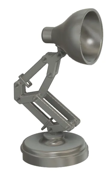
Design
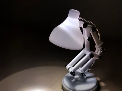
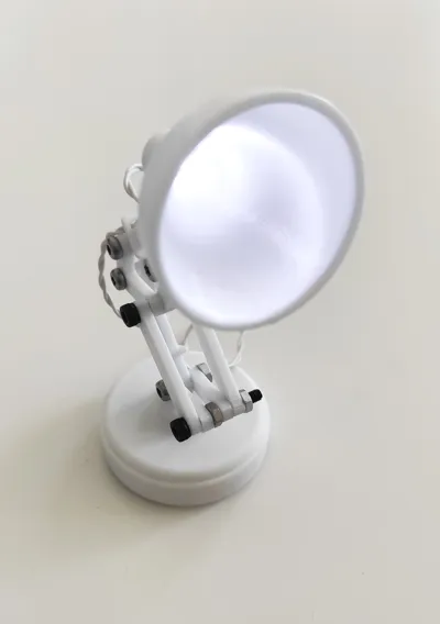
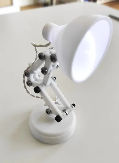
This tiny project is inspired by the design of Pixar's Luxo Jr. The tiny lamp is fully articulated and printable as both a decorative figurine (without LED) and a tiny working lamp with an LED - both options are provided.
The lamp stands around 10 cm tall with a 4.5 cm footprint.
The LED in my design is powered by a CR2032 coin cell battery in a Sparkfun Lily pad coin cell holder which also has a built-in on/off switch. The battery is hidden away inside the lamp base.
You can use any power supply that supplies about 3V and design your own base or other solution and print all other parts.
Materials
Needed hardware beside the 3D printed parts:
- 6x M3x12 screw
- 2x M3x18 screw
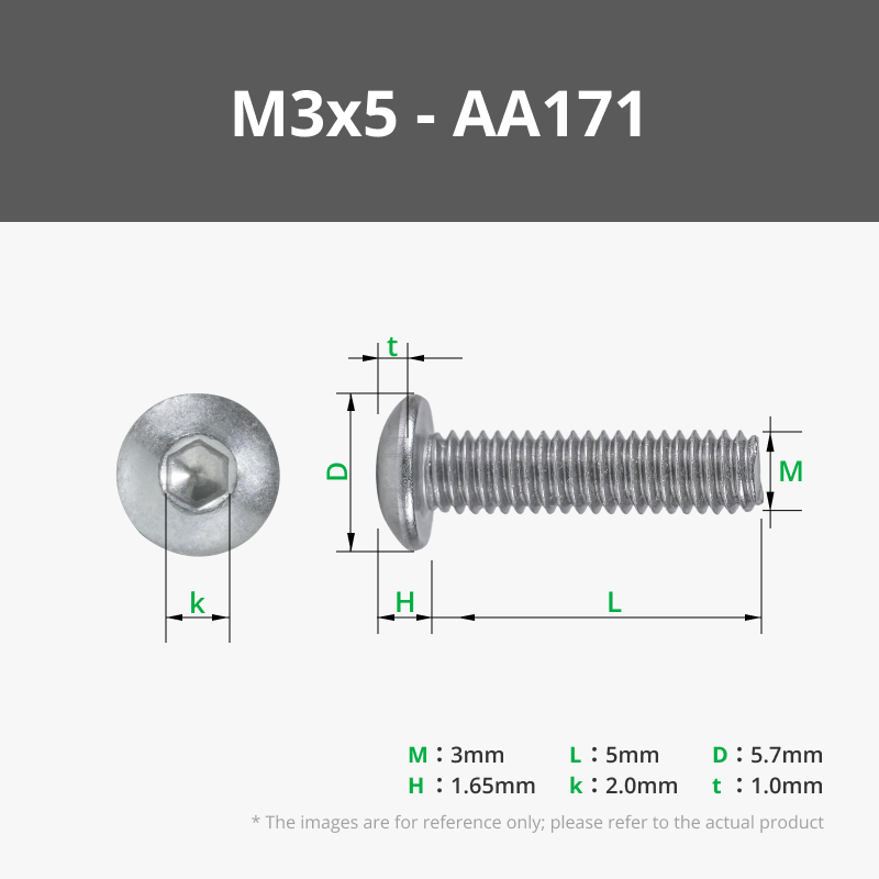
- 2x M3x5 screw
- 9x M6 hex hut
- 1x white LED
- Resistor (10-100Ω)
- Sparkfun Lilypad coin cell holder (or other ≈3V power supply)
- Thin wires
Assembly
Step 1
Assemble lower link 1 and the base. It can be a tight fit, but screwing it in will work.

Step 2
Use a M3x12 screw and an M3 hex nut to assembly one lower link 2 on either side of lower link 1. It can be useful to use a screwdriver.

Step 3
Put a wire fastener around lower link 1.
If you wish to print the model without later adding an LED, you can skip this step.

Step 4
Mount a middle link on either side of lower link 1 with a M3x12 screw and nut. Pay attention to the orientation of middle link.

Step 5
Assemble lower rod on the outside of each lower link 2. Insert an M3 hex nut into the space in the middle before securing it all together with a M3x18 screw.

Step 6
Insert short upper rod in the space between middle link and move the unfastened ends of the two lower rods up to middle link. Secure everything together with an M3x18 screw. Make sure to use the long side of middle link for this step.

Step 7
Place long upper rod in the space between the two middle links and assemble with an M3x12 screw.

Step 8
Put a wire fastener around long upper rod.
If you wish to print the model without later adding an LED, you can skip this step.

Step 9
Take the two upper links and sandwich them around long upper rod and short upper rod and align the holes. Use an M3x12 screw through each hole and tighten with hex nuts.

Step 10
Cut the legs off the LED leaving just a tiny bit enough to solder each leg to a thin wire. Use a bit of shrink flex or insulating tape around each solder. Lead the wires through the hole in the lamp shade and either glue the LED to the shade or if the shrink flex or tape provide enough friction, glue will not be necessary.
If you wish to print the model without later adding an LED, you can skip this step.

Step 11
Mount the lamp shade with an M3x12 screw through the two upper links.

Step 12
Twist the wires and lead them through the wire fasteners.
If you wish to print the model without later adding an LED, you can skip this step.

Step 13
Solder the wires to the power supply. Include a resistor (10-100Ω) between one end of a wire and one of the poles on the power supply. Make sure to solder the correct wire to + as the current can only flow one way in an LED. Check by turning on the power supply and touch one wire end to + and the other to - and see if the LED lights up. If it does not - switch the wires between + and -.
If you wish to print the model without later adding an LED, you can skip this step.

Step 14
If you use the Lilypad coin cell holder as the power supply, the part battery fixture is specifically designed to fit it inside the base. Put the coin cell holder upside down in the battery fixture and orient it so that the on/off button is accessible. Secure the battery fixture to the base with two M3x5 screws.
If you wish to print the model without later adding an LED, you can skip this step.

Final assembly
Congratulations! Your tiny articulated desktop lamp is finally completed.

Boost Me (for free)
Love this design? Give it a boost and help it shine!
License
You shall not share, sub-license, sell, rent, host, transfer, or distribute in any way the digital or 3D printed versions of this object, nor any other derivative work of this object in its digital or physical format (including - but not limited to - remixes of this object, and hosting on other digital platforms). The objects may not be used without permission in any way whatsoever in which you charge money, or collect fees.
Comment & Rating (2)