
Garage Distance Sensor w/ LED Indicator
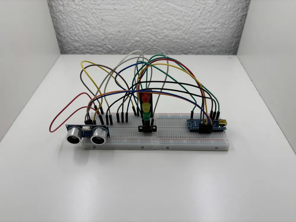
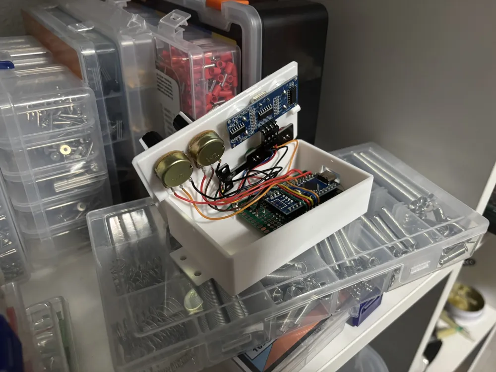
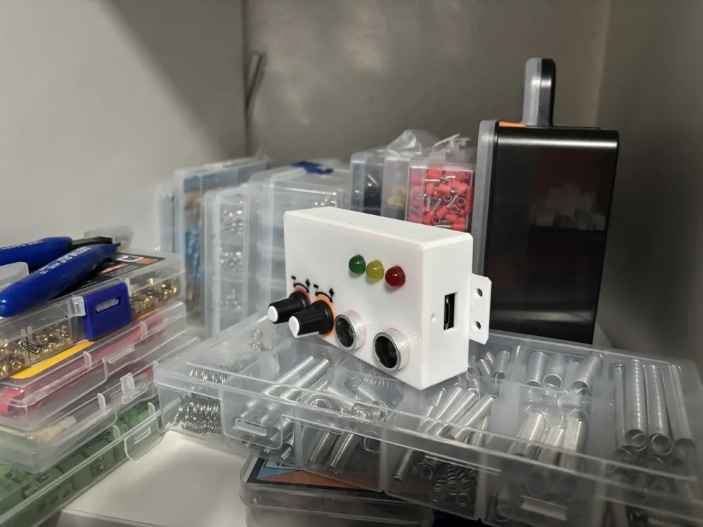
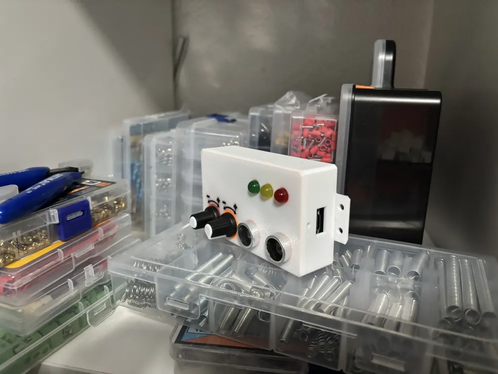
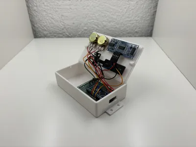
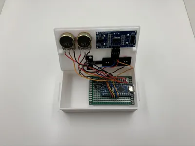
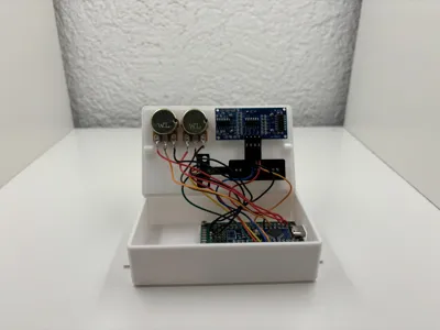
Print Profile(1)

Bill of Materials


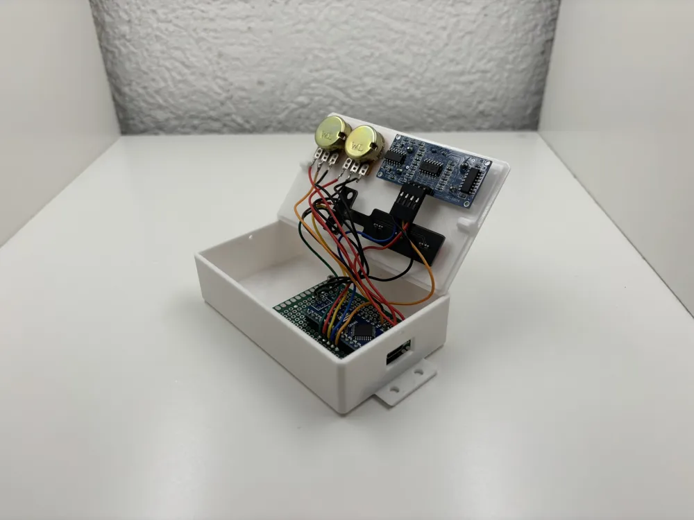
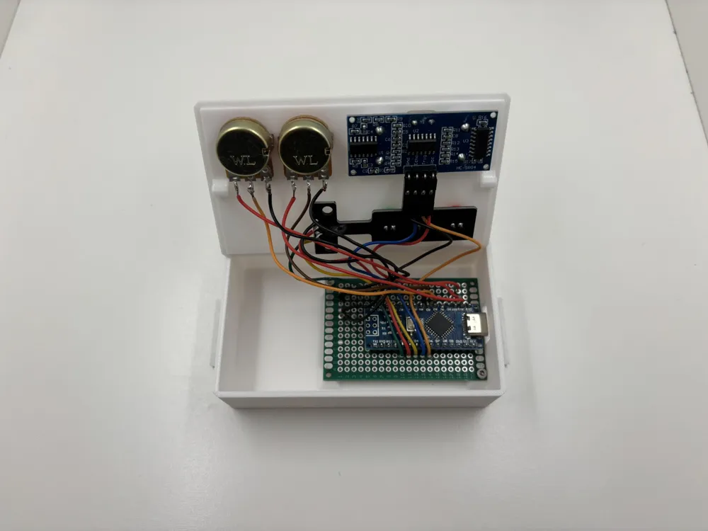
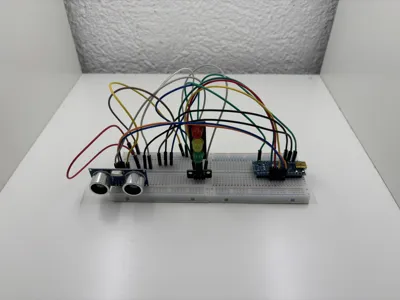
- Arduino Nano x 1: Arduino Nano V3 if possible
- Potentiometer (K Value irrelevant) x 2: As a Dial with a Knob, not Linear.
- HC-SR04 Ultrasonic sensor x 1: Can be found separately as Part of a Set.
- Wire (Red) x 1: For Power (VCC / 5v / 3.3V)
- Wire (Black) x 1: For Ground
- Wire (Random Color) x 1: To Wire the Potentiometer and the LEDs
- PCB Board (16x14 Holes) x 1: At least 16x9 Holes. It can be found by Searching for "PCB Board Perforated Grid Board"
- Pin Headers - Female - 16x1 (16 Long and Single Row- Thought Hole) x 2:
- LED Traffic Light Module x 1: Can be Substituted with 3 separate LEDs (Red, Yellow, Green)
Description
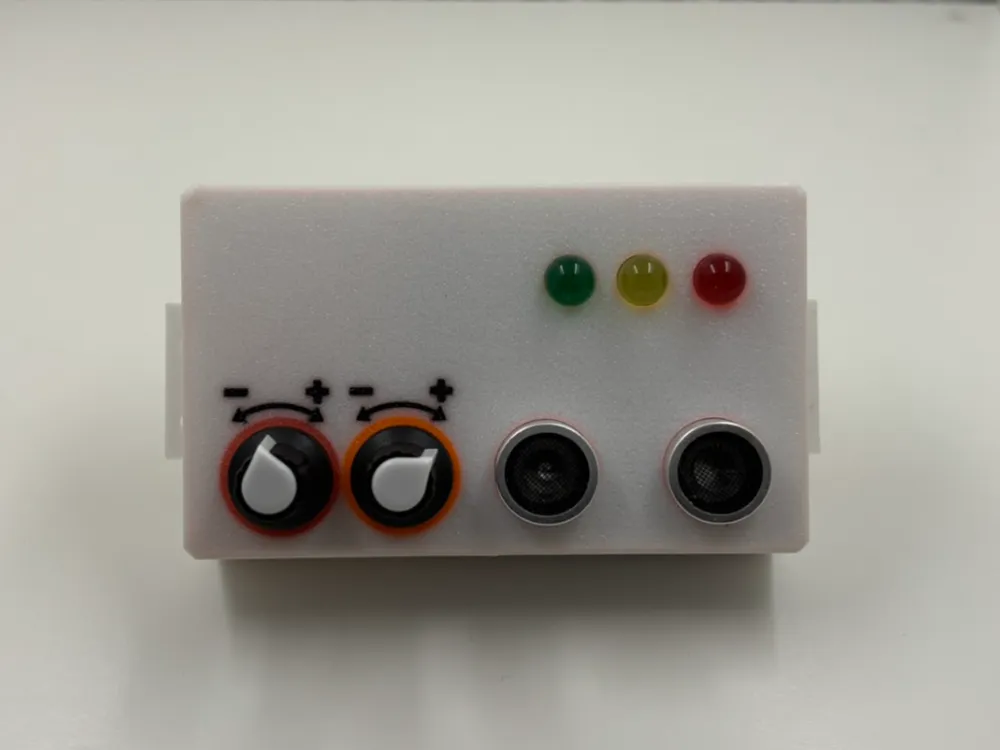
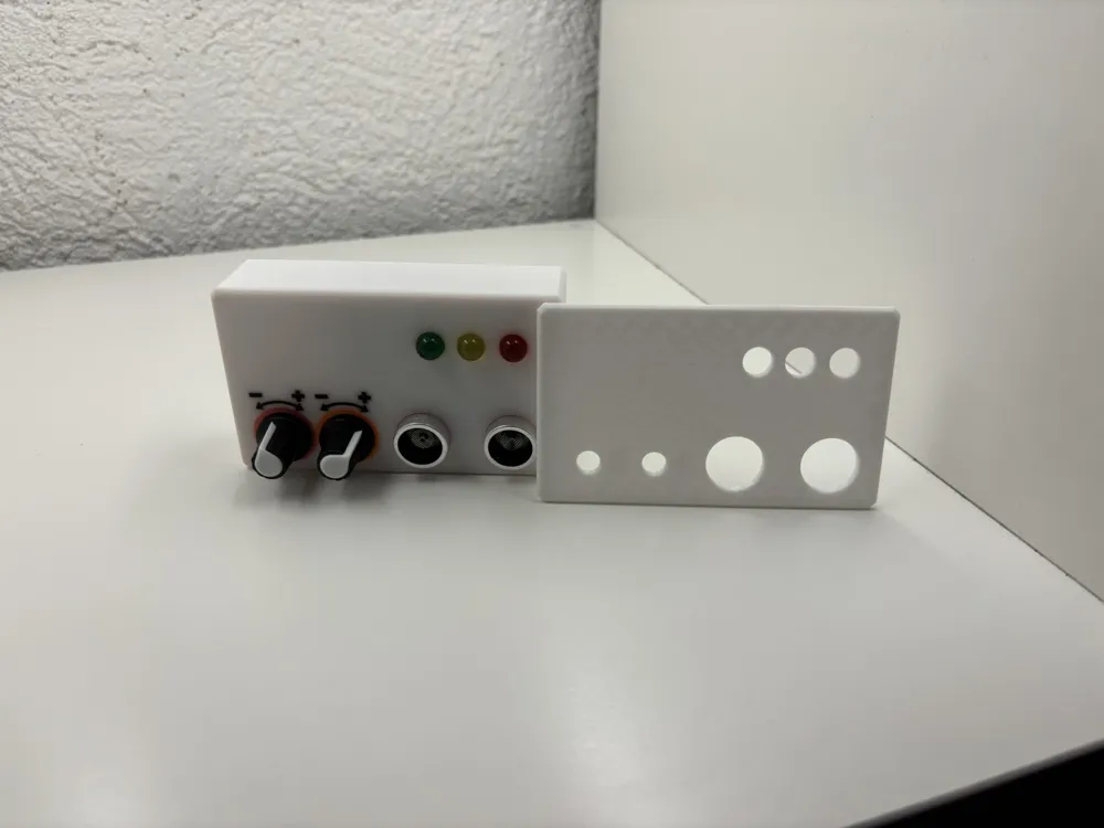
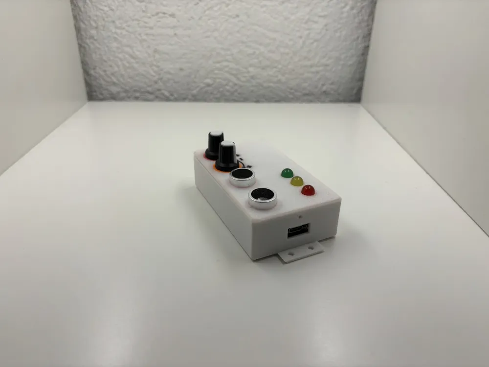
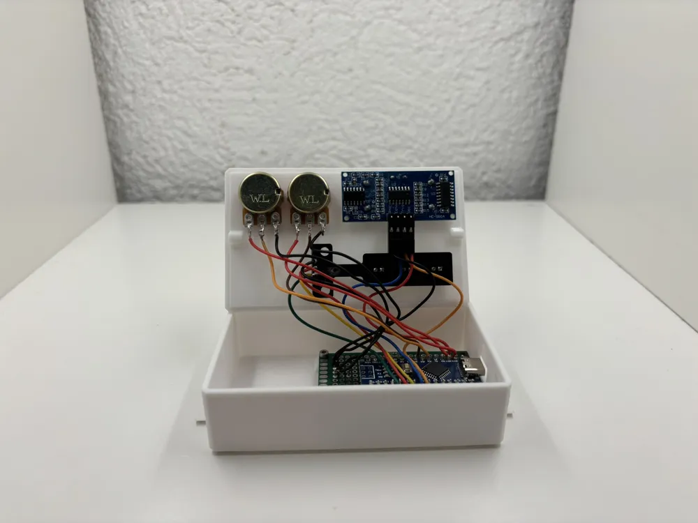
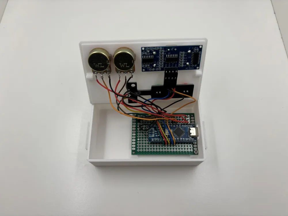
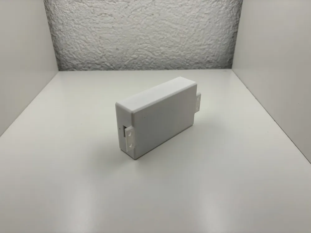
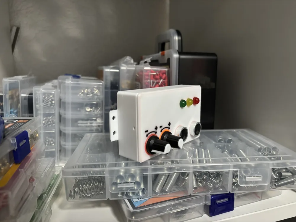
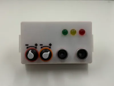
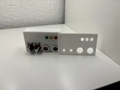
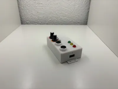
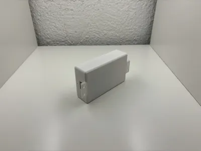
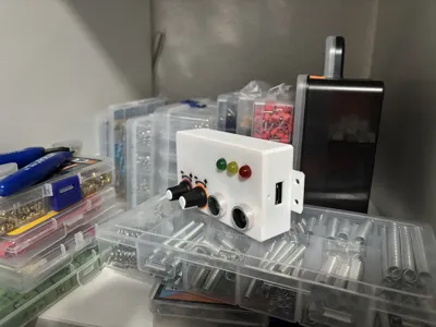
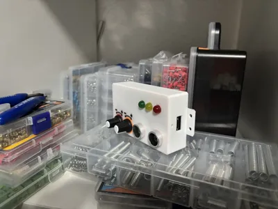
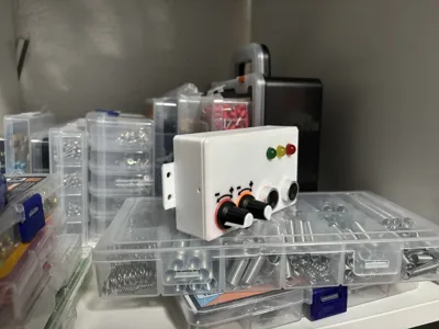
GarageMate-DST-G1V1 - Garage Distance Indicator with LED
Mount the GarageMate to the Wall of your Garage and use the Indication Lights to guide you as close as you like towards the Wall.
Features:
- The Distance for the Red and Yellow LEDs are adjustable!
- Precise Measurement (+- 1cm)
Code
The Code is available on Github!
Load a new Project in the Arduino IDE.
Copy the Code from “main.ino” to your Project.
Flash the Microcontroller!
The Code is for free, however you can support this Project and more Projects in the Pipeline by Boosting this Model!
Microcontroller
I can recommend a Arduino Nano (V3).
You can easily Substitute any Microcontroller and change the Pins. The Code will still Work!
BOM (Bill of Material)
Check the Bill of Material bellow the Descirption Box!
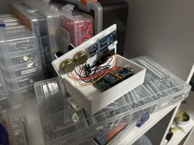
This is meant to be a Project to Tinker and learn how the Solder.
PCB and Pin-Headers
The PCB and Pin-Headers are not required, tho it makes it way easier to tinker with and fit it in the Board in the Box nice and tight.
LED Traffic Light Module
Please note that you will need NO Resistors for any LED Traffic Light Module. Those come with Resistors build in!
If you substitute the LED Traffic Light Module with 3 separate LEDs than you will NEED Resistors. The Arduino Nano provides 3.3 Volts through the GPIO Pins which will fry the LEDs in the longrun!
License

You shall not share, sub-license, sell, rent, host, transfer, or distribute in any way the digital or 3D printed versions of this object, nor any other derivative work of this object in its digital or physical format (including - but not limited to - remixes of this object, and hosting on other digital platforms). The objects may not be used without permission in any way whatsoever in which you charge money, or collect fees.


Comment & Rating (1)