
Lab Jack / Scissor Lift
Print Profile(3)


Bill of Materials
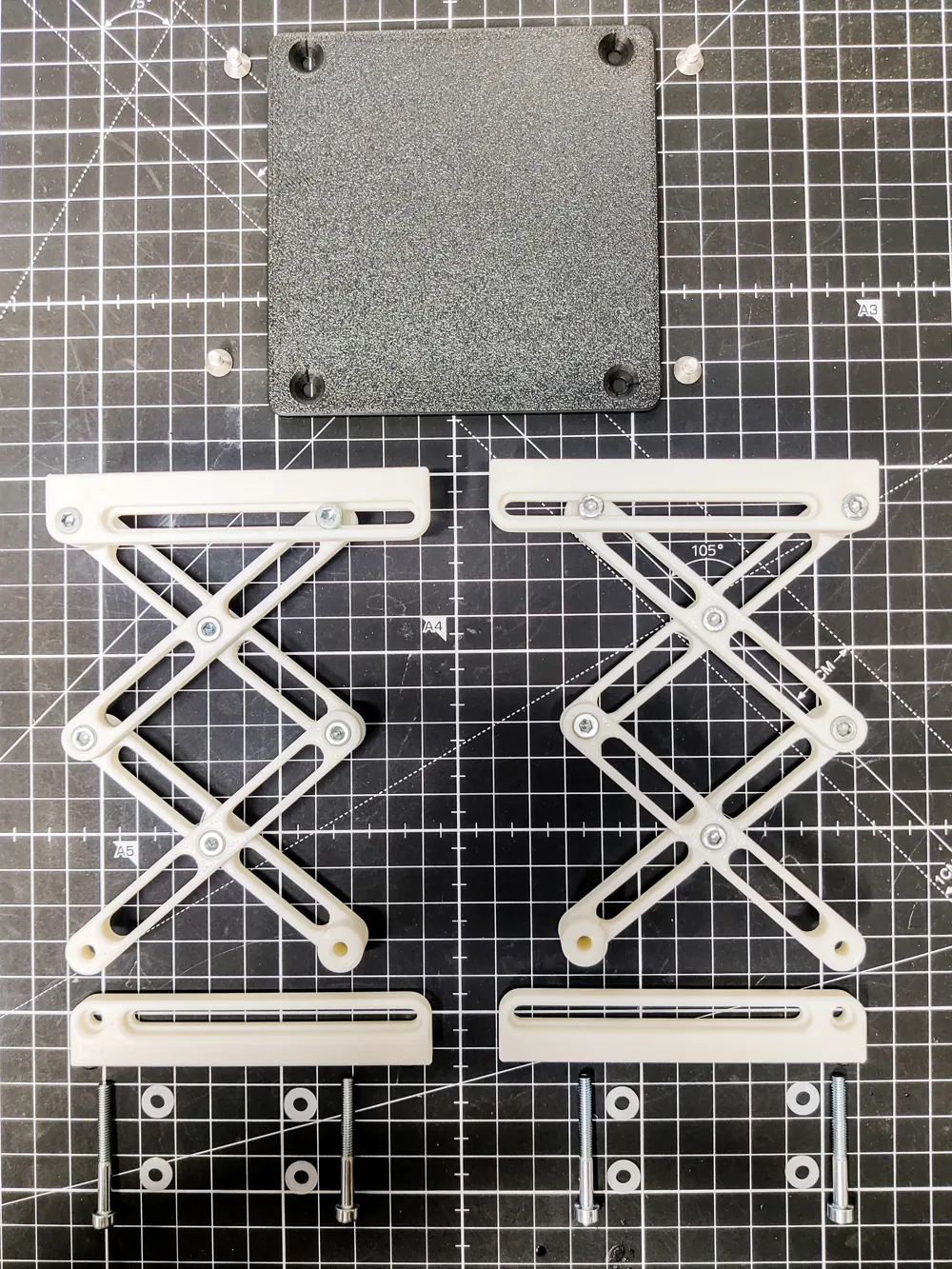
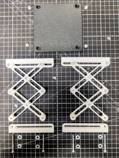
- M4x12mm Cylindrical Head Machine Screw x 12: Attaches beams together
- M4x35mm Cylindrical Head Machine Screw x 4: Attaches leg to slots
- M4x5mm Countersunk Machine Screw x 4: Top plate
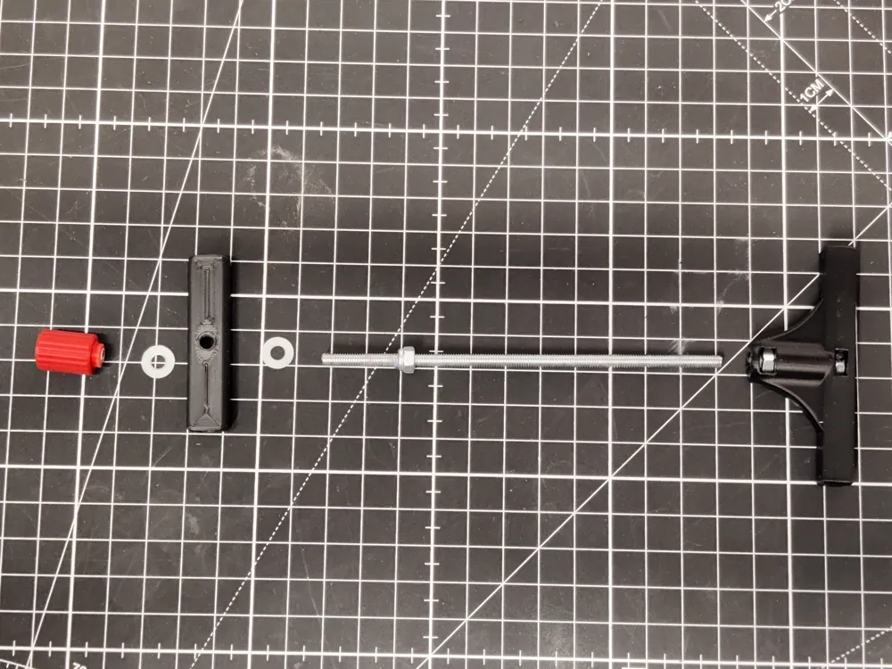
- M4x110mm Threaded Rod x 1: Pull rod assembly
- M4 Hex Nut x 2: Pull rod assembly
- M4 Lock Nut x 1: Pull rod assembly
- M4 Nylon Washer x 20: Insert between all connections between beams
Description
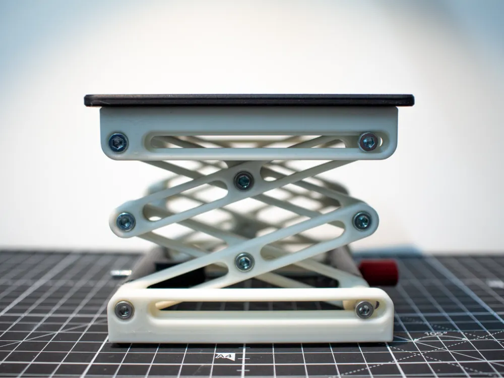
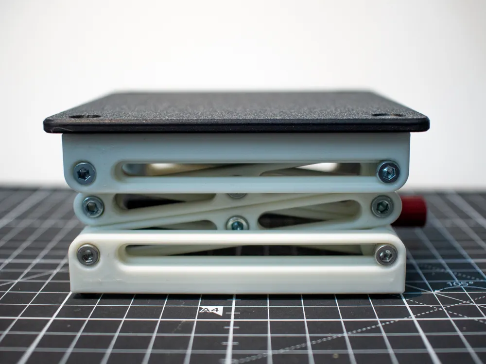
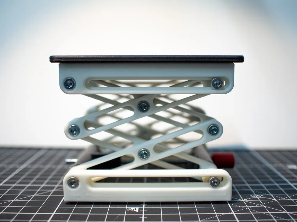
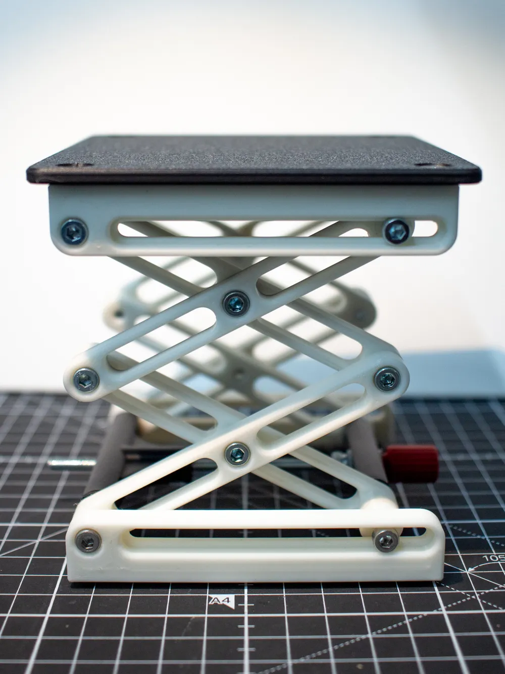
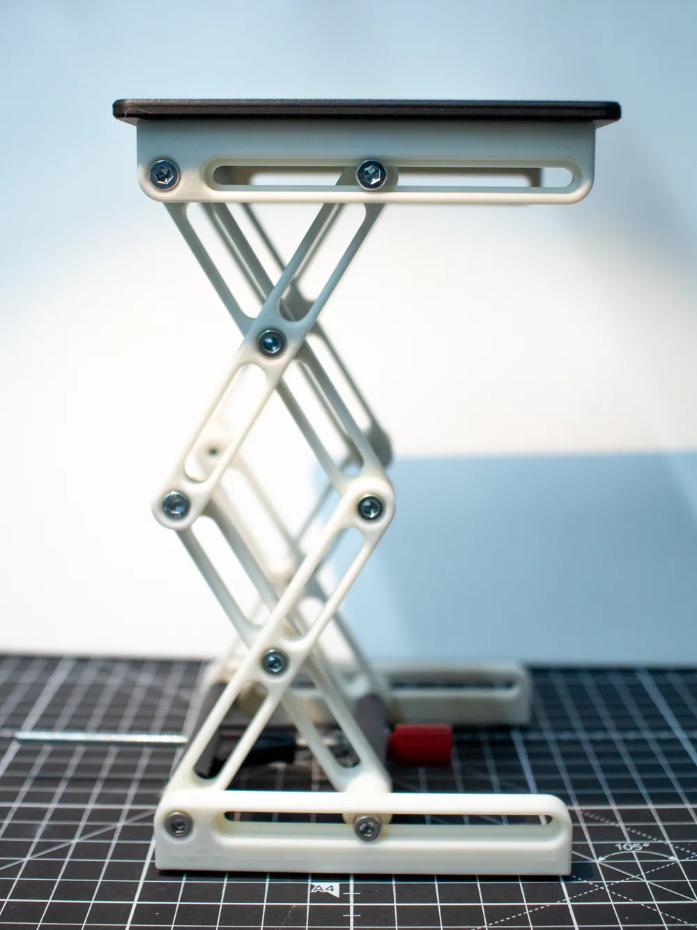
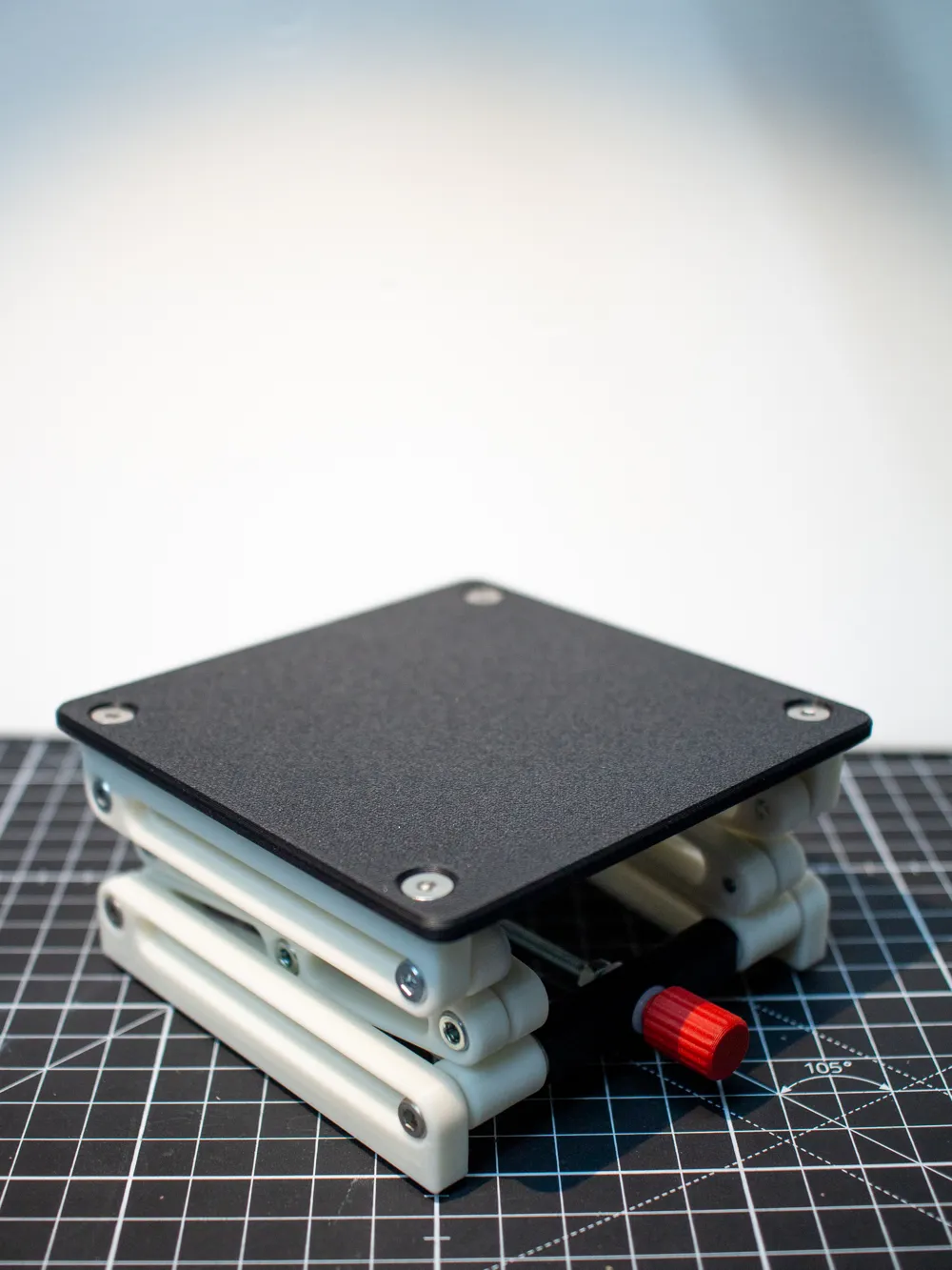
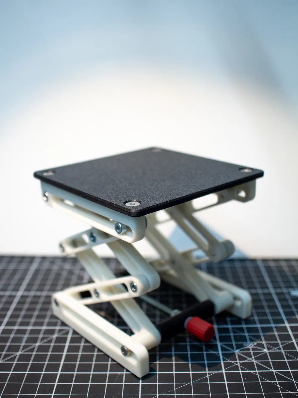
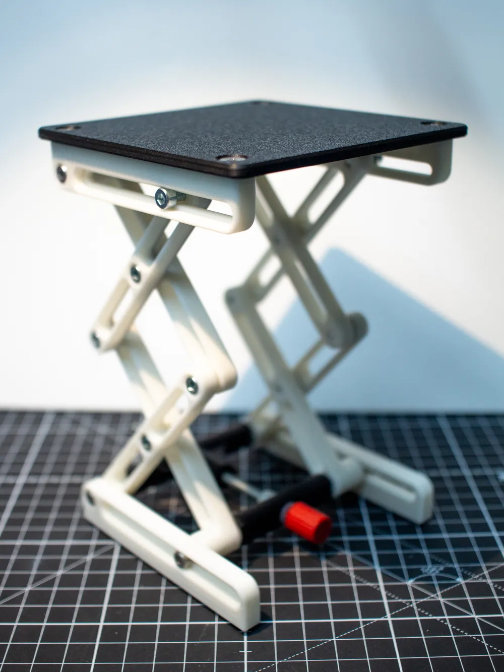
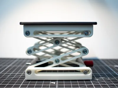
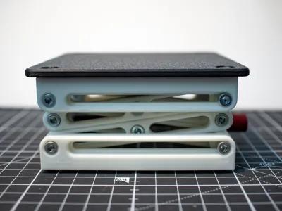
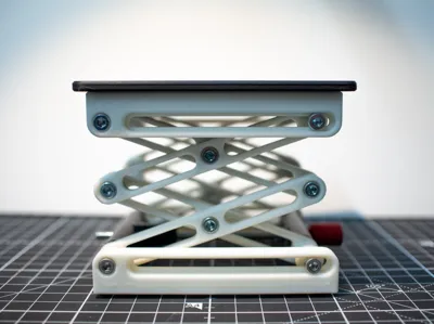
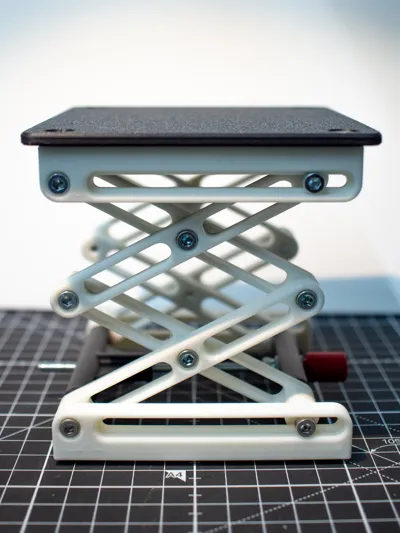
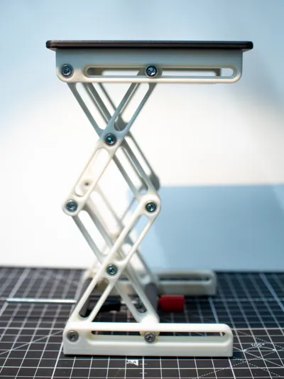
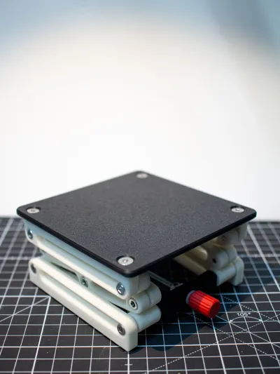
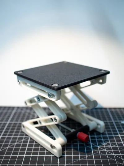
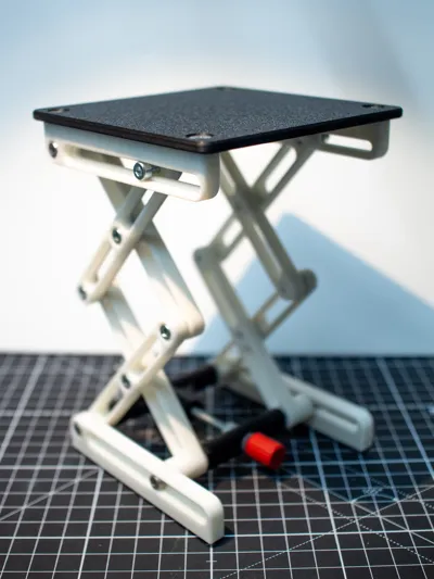
This is a laboratory jack (also known as a scissor jack or lab lift), used to raise or lower equipment in a controlled, stable manner.
It is designed to use standard M4 hardware in place where plastic does not cut it.
Print in PLA(+), to maximize strength. Matte PLA might delaminate when inserting screws. No supports required.
While it can support more than 1.4kg (it has not been tested to destruction), it is much more suited for loads up to about 600 grams.
Assembly
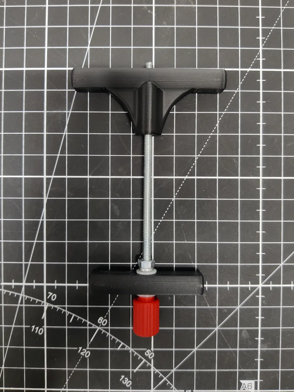
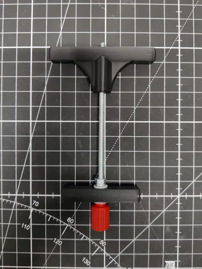
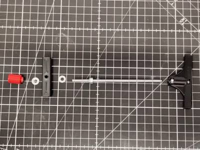
Start with the pull rod assembly:
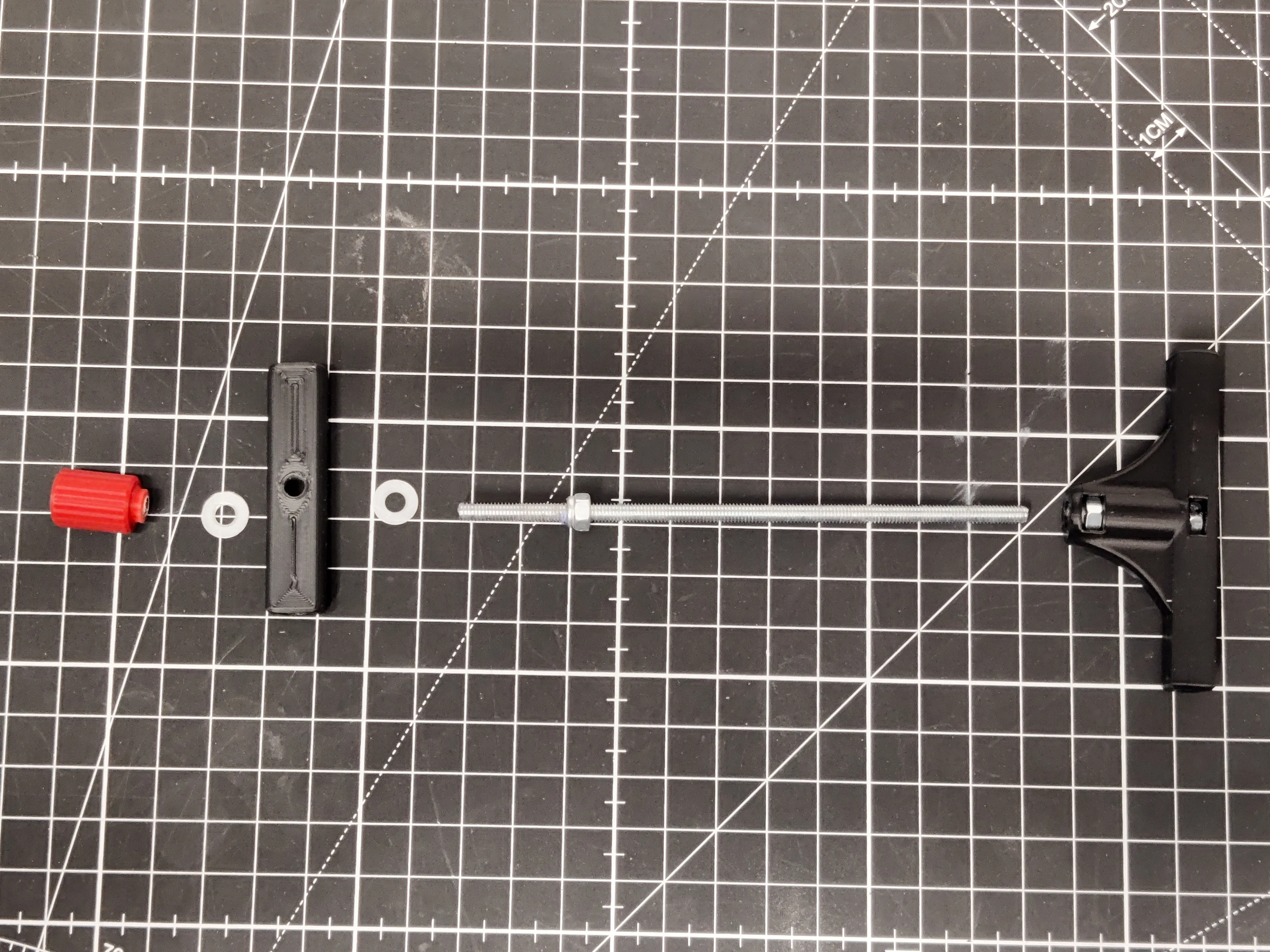
- Cut M4 threaded rod to 110mm
(Add a nut before cutting, that way you can screw the nut over the cut end and reform the threads) - Add locknut, about 25mm from one end, with the round part pointing out
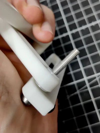
- Insert nuts in the T shaped part (The left one on the photo is supposed to be a bit loose)
- Add washer, the the small bar, washer, and screw on the knob.
(It helps if you put two nuts on the other end, and tighten them against each other. Then you can use a wrench to grip the rod)
Turn it over so you don't have to see those nuts.
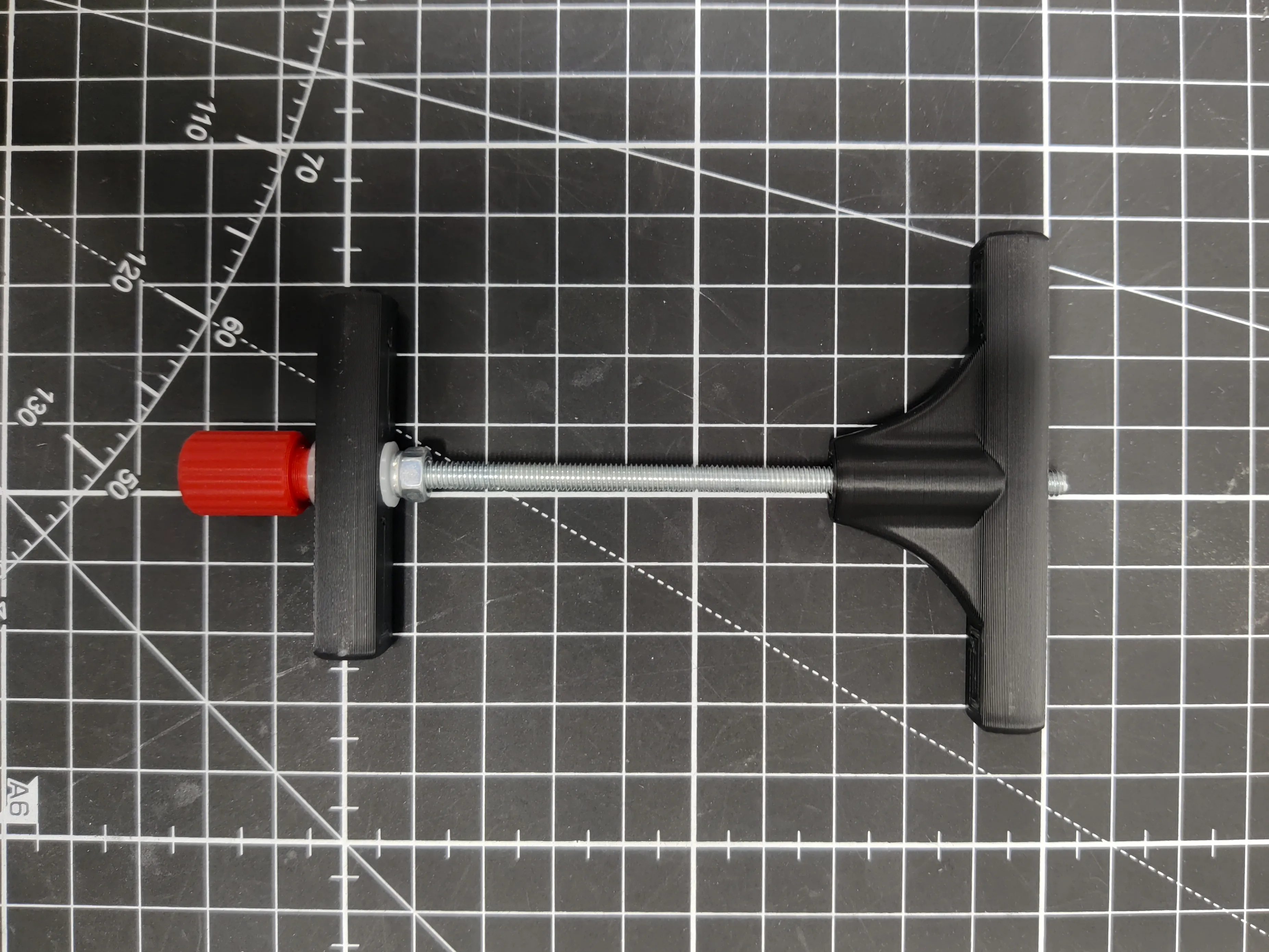
This is where the fun starts:
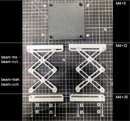
You need to assemble two legs, and they should be mirrored.
The beams are named for the types of holes they have:
- tte: tap-tap-extension
- cct: countersunk-countersunk-tap
- tteh: tap-tap-extension-hole
- cch: countersunk-countersounk-hole
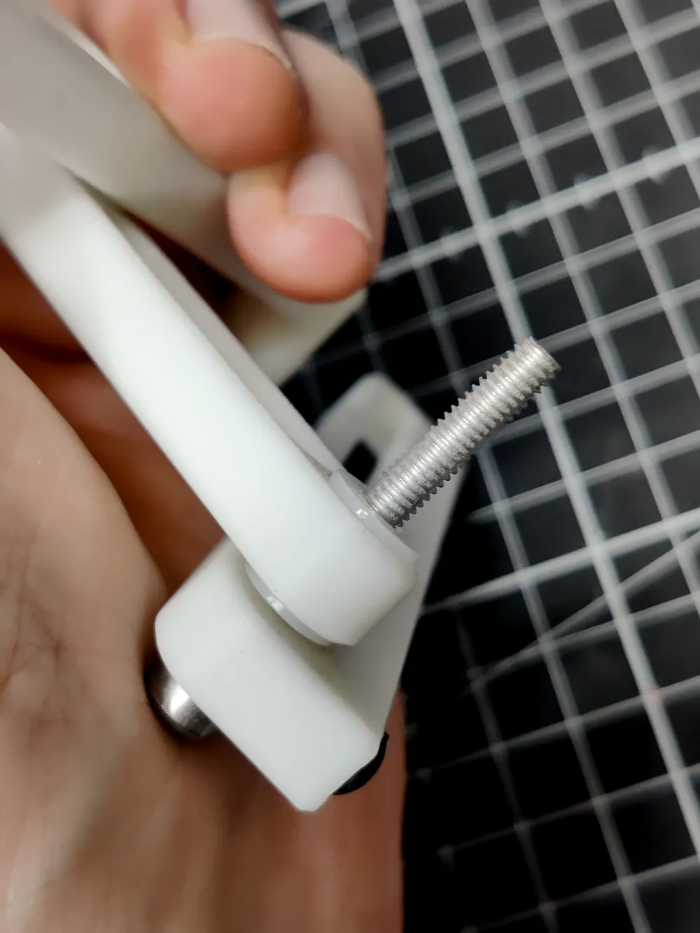
A screw goes in a countersunk hole, and is screwed into a tap hole with a nylon washer in between.
It takes a bit of force to screw them in, the connection is supposed to be locked in place.
Tighten each screw until the joint can't rotate anymore, then just back the screw out a little but until it moves freely, but with minimal play.
Next, attach the pull rod assembly to the legs. This is where you determine which side of this mechanism is stationary. (I did it the wrong way around while reassembling this for the pictures, it's nicer if the knob is on the stationary end.)
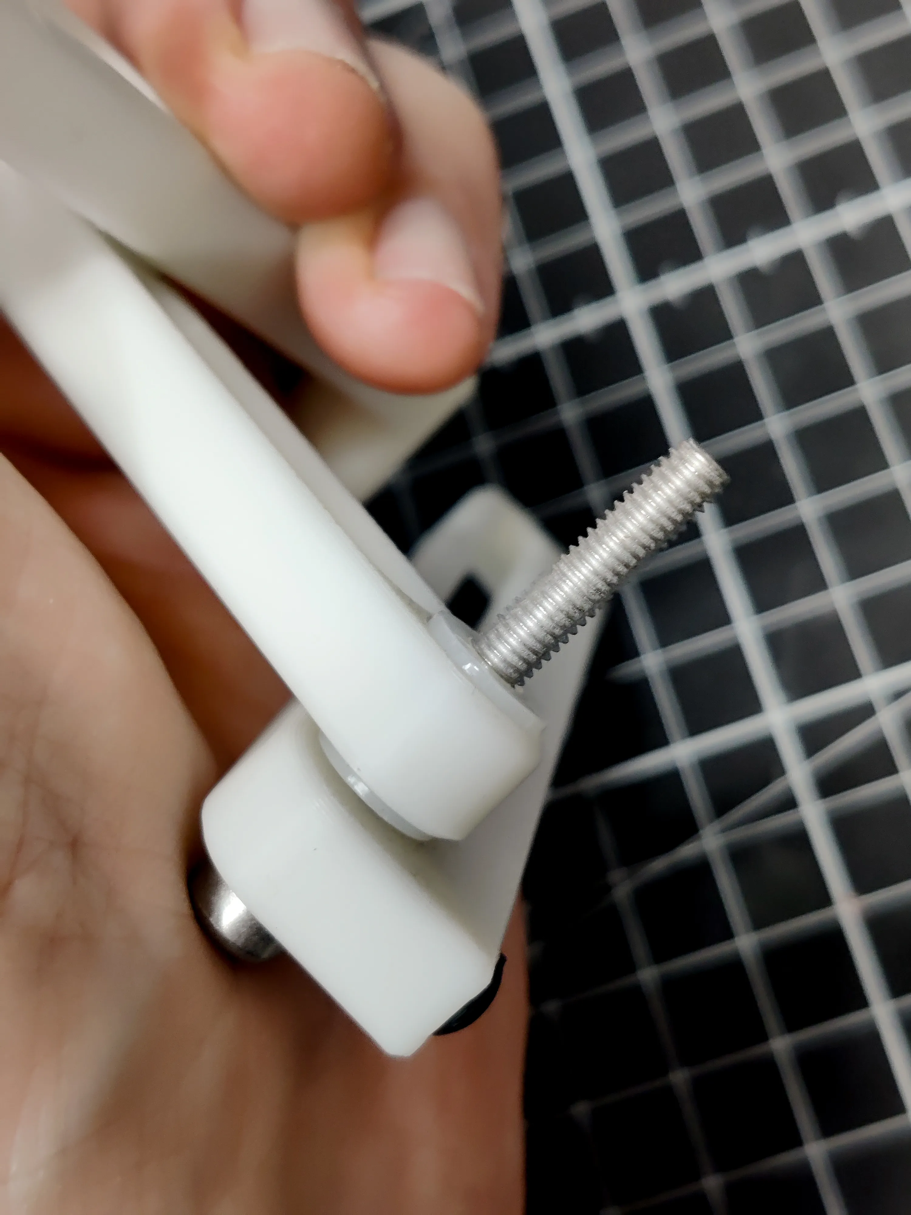
Insert a 35mm bolt, add nylon washers in between each member, and screw into the cross member.
The bolts that go through the slots screw in to the T shaped crossmember.
Finally, attach the top plate with the M4x5mm screws.
To make everything smoother, you can lubricate the slots with some vaseline or grease of choice. (A little bit goes a long way here)
License

You shall not share, sub-license, sell, rent, host, transfer, or distribute in any way the digital or 3D printed versions of this object, nor any other derivative work of this object in its digital or physical format (including - but not limited to - remixes of this object, and hosting on other digital platforms). The objects may not be used without permission in any way whatsoever in which you charge money, or collect fees.


Comment & Rating (64)