
HABB - Home Assistant Button Box - ESPHome


Print Profile(2)


Bill of Materials
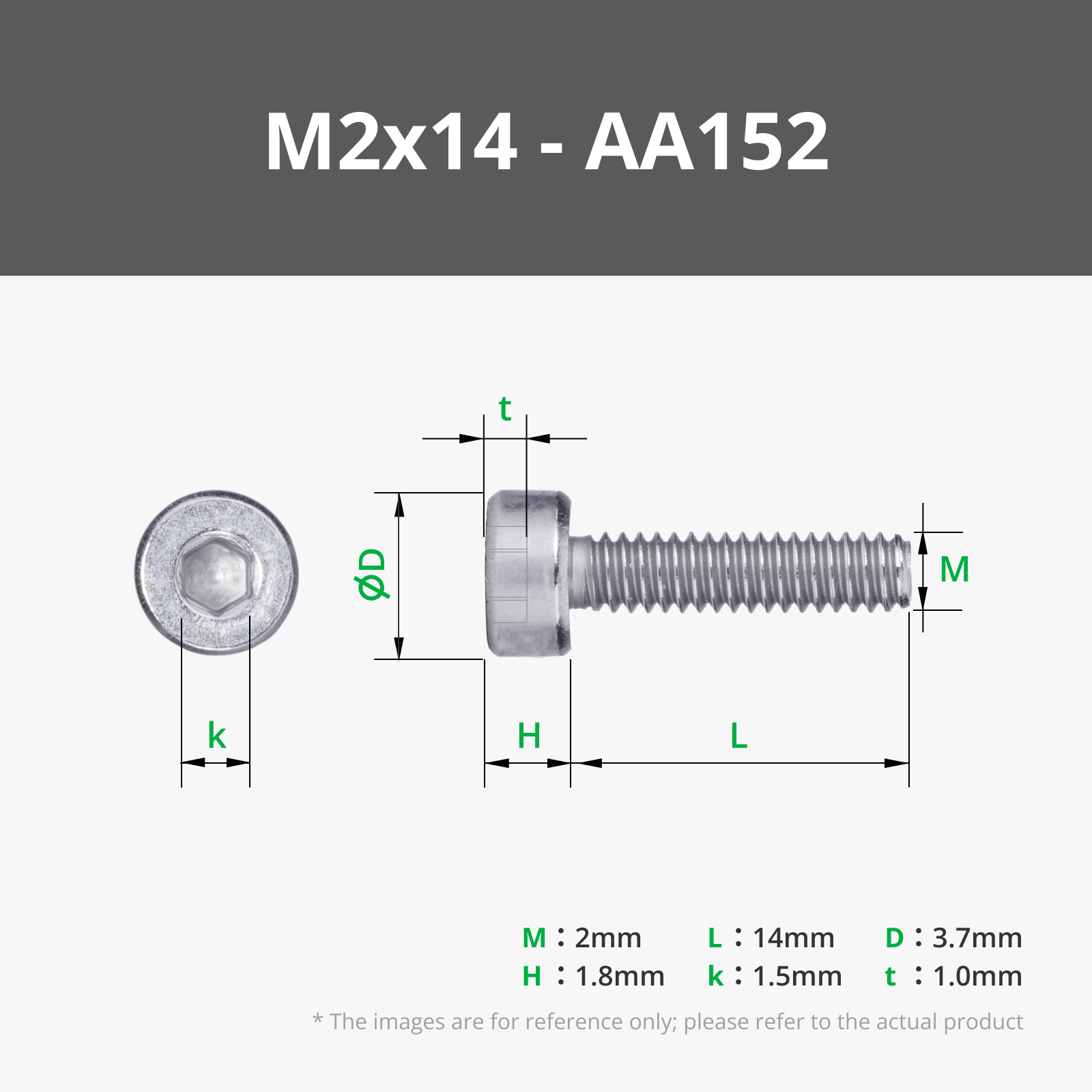
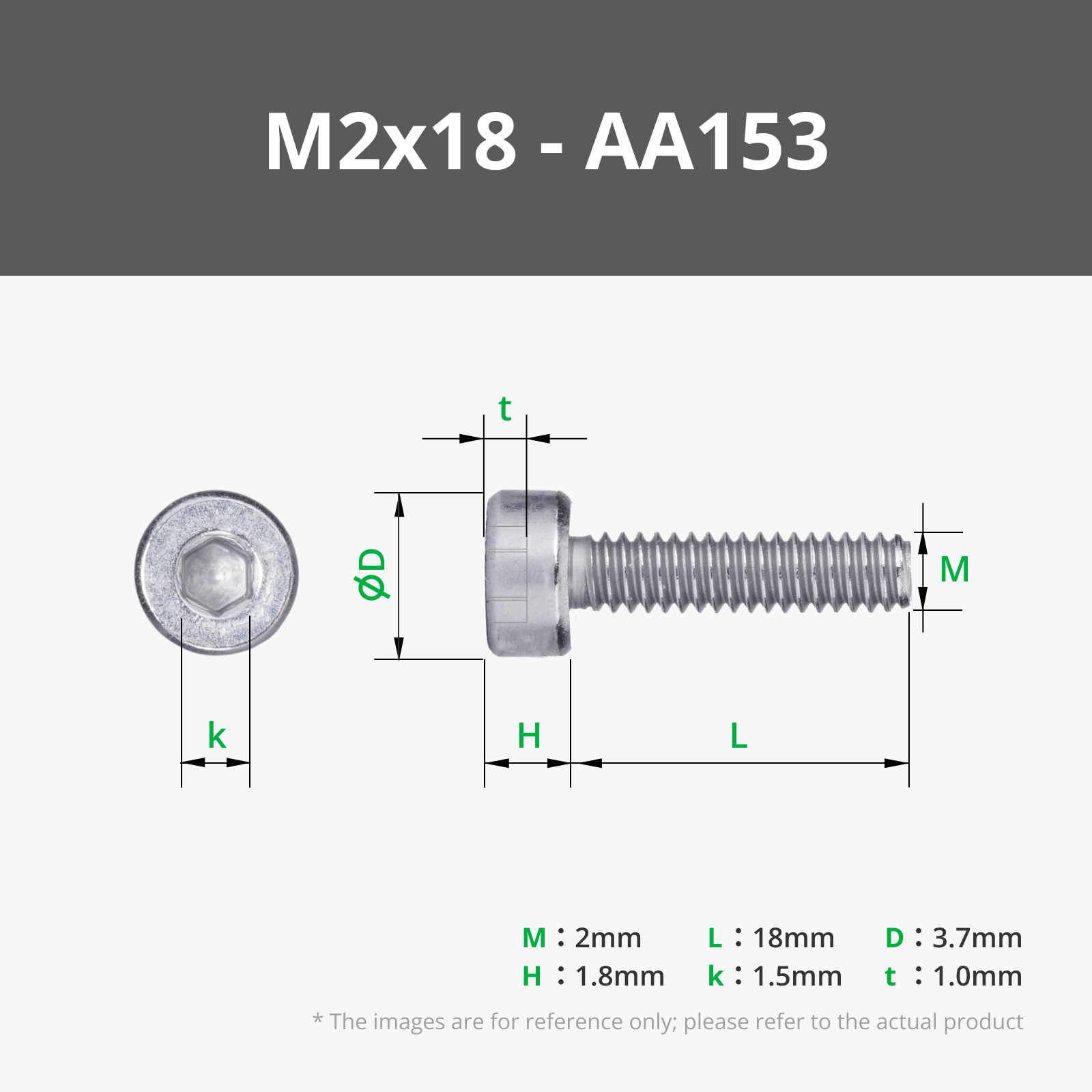


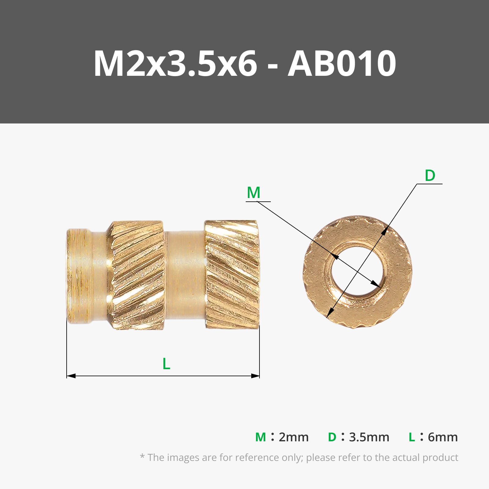



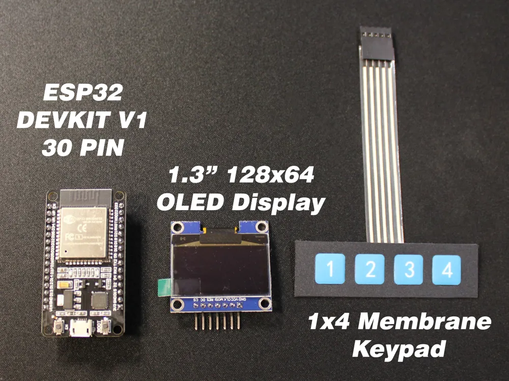
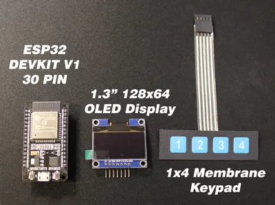
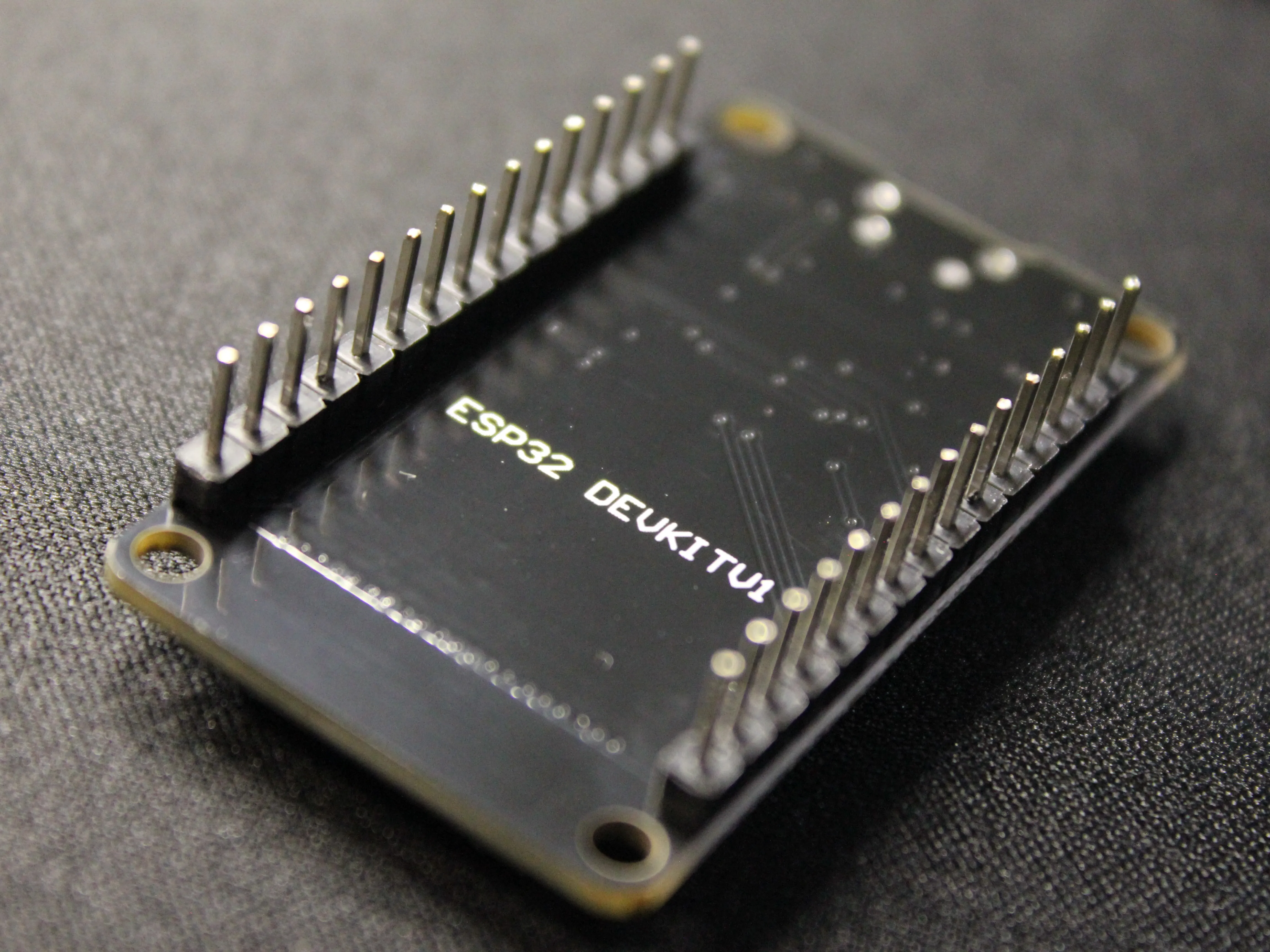
- ESP32 - DEVKIT V1 x 1: 30 Pin Model
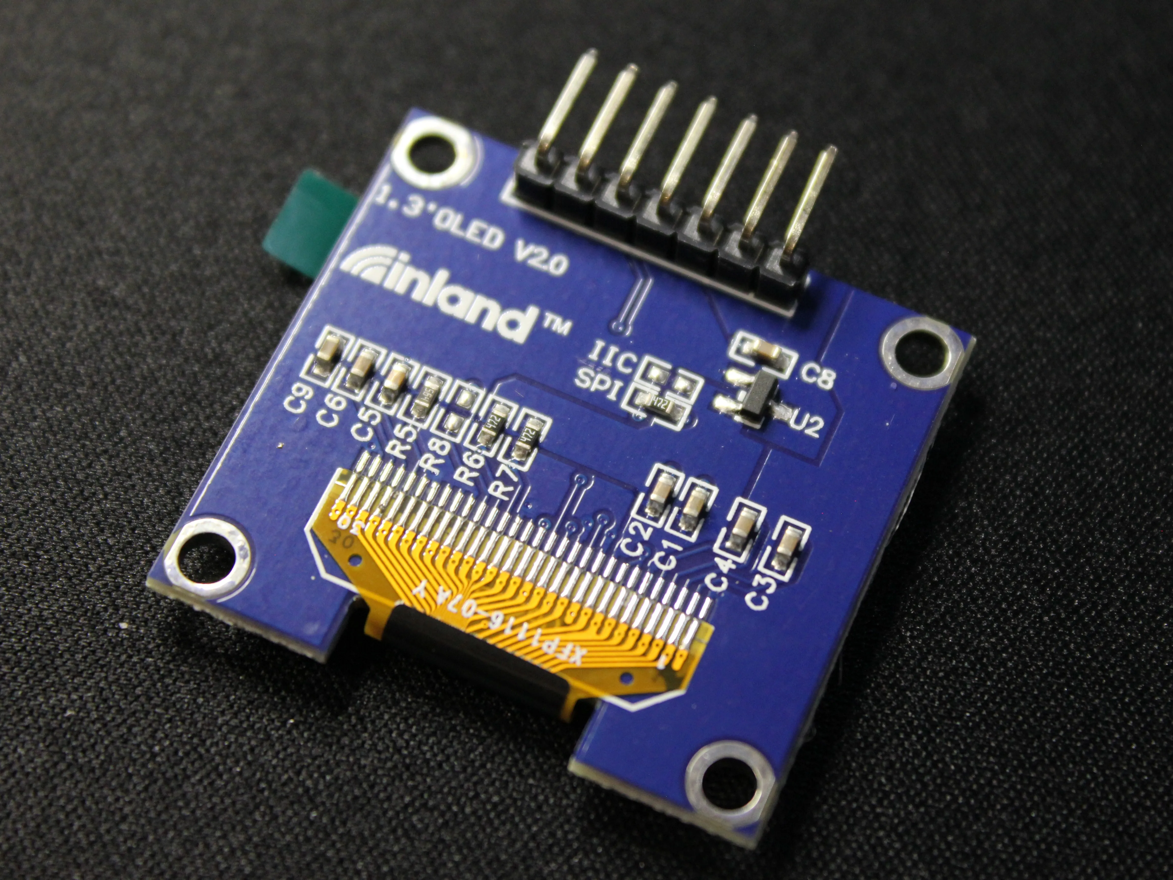
- 1.3" OLED Graphic Display x 1: 128x64 with mounting holes
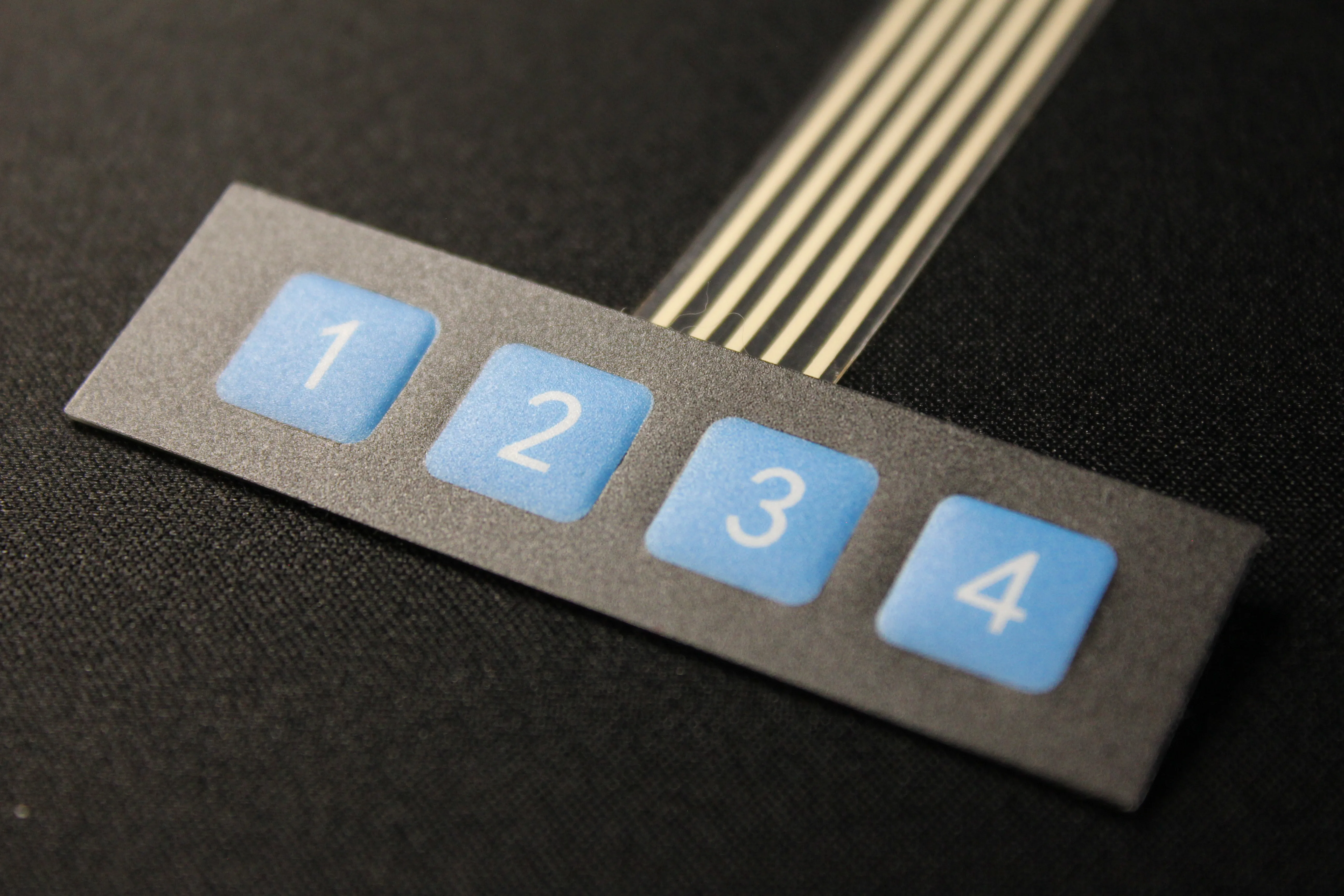
- 1x4 Membrane Keypad x 1: 5 Wire Connection
Description
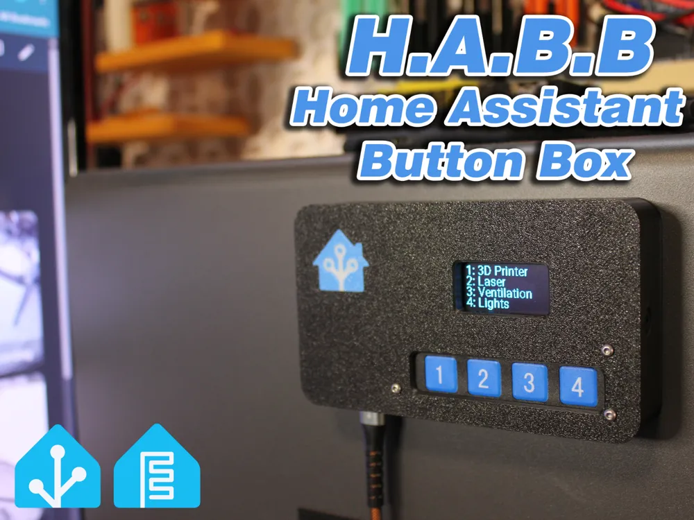
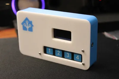
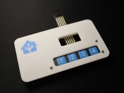
H.A.B.B – Home Assistant Button Box
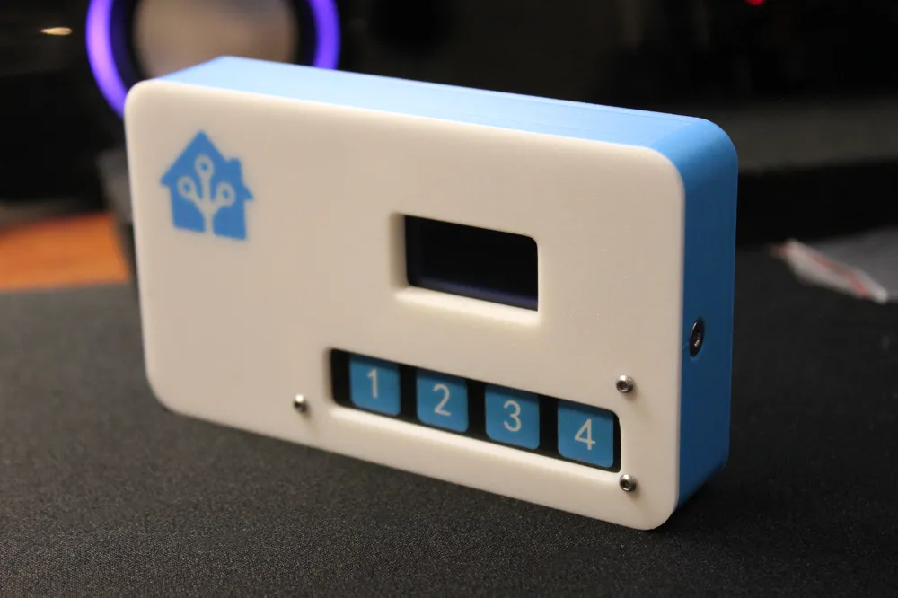
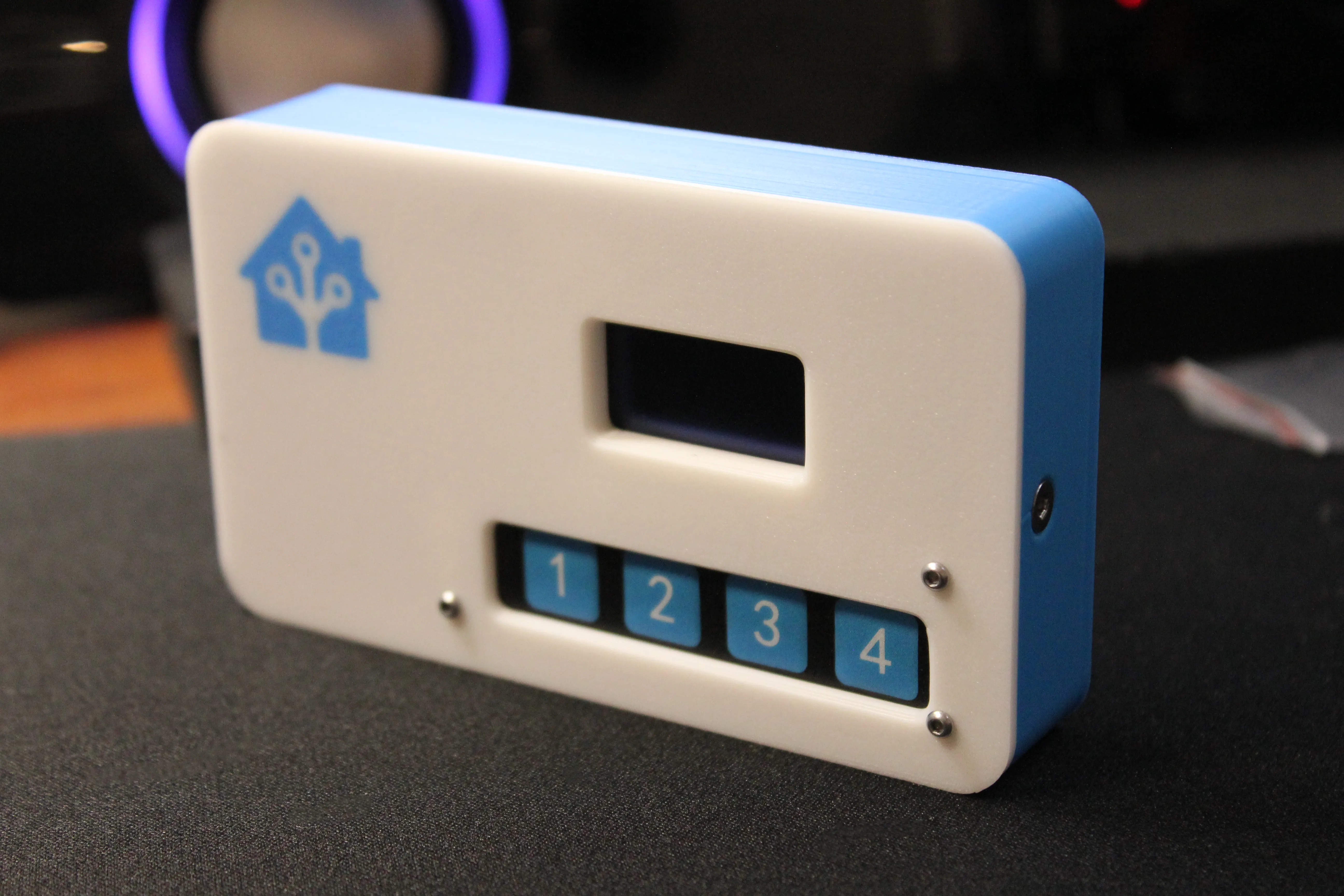
A customizable 4-button smart control panel case for ESP32 + OLED display
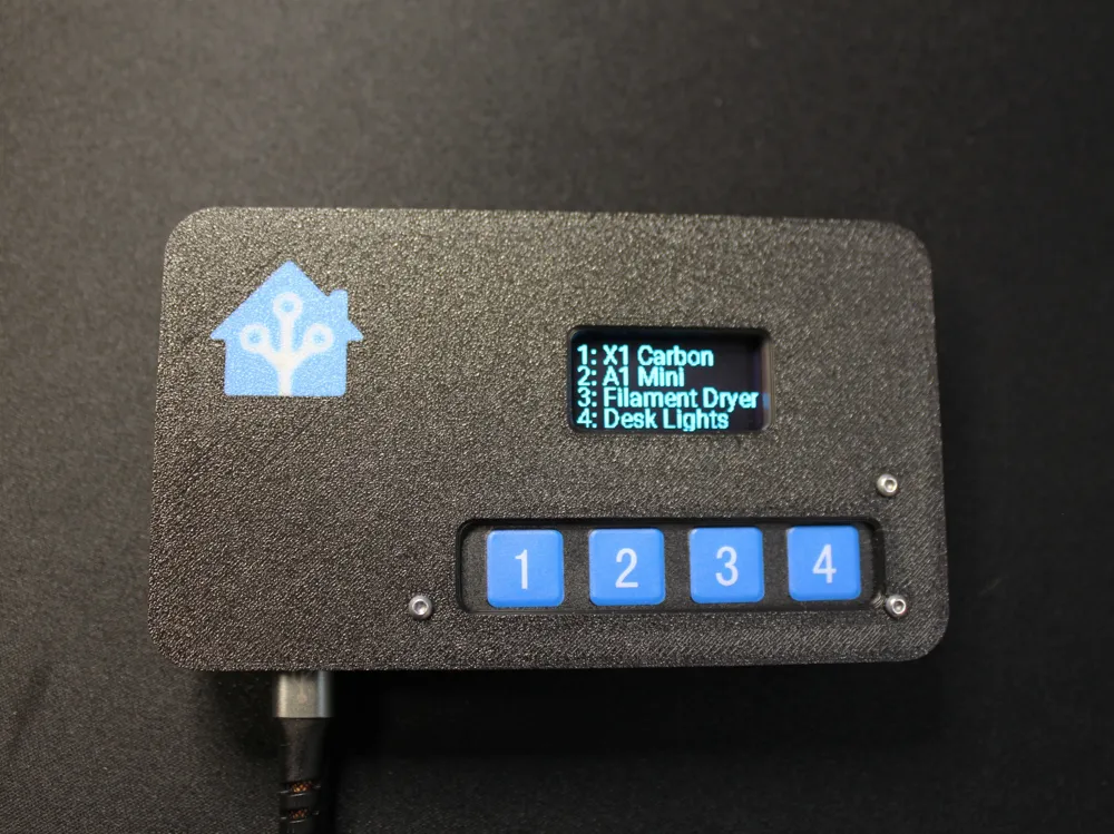
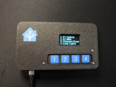
I designed this for a simple, reliable smart home control interface using an ESP32 DevKit V1, a 1.3” 128x64 OLED Screen, and a 1x4 Membrane Keypad. It connects to Home Assistant via ESPHome and can trigger any scene, script, or automation with the push of a button.
This button box is perfect for controlling zones in a workshop, studio, or bedroom—turn on printers, ventilation, lights, or even run automations. I built this mainly for my own workspace to quickly trigger automations without having to pull out my phone or open the HA dashboard. It’s compact, clean, and sticks right to any metal surface with magnets.
YAML: I've included a source code file, but wanted to include the basics here - Full YAML is at the bottom of this post!
Specs:
Size: 115mm x 67mm x 22mm
Designed for:
ESP32 DevKit V1 (30-pin)
SH1106 1.3" 128x64 OLED Display (SPI)
Adafruit-style 1x4 membrane keypad
Power: USB-powered through a passthrough cutout
Mounting: Fits 4x 10x2mm magnets in the back (optional but recommended)
Assembly:
ESP32 clearance: The case is just 22mm thick, so either use an ESP32 without headers or bend the pins you need and snip the rest
I highly recommend assembling and testing the electronics before fully assembling this model!
Step 1:
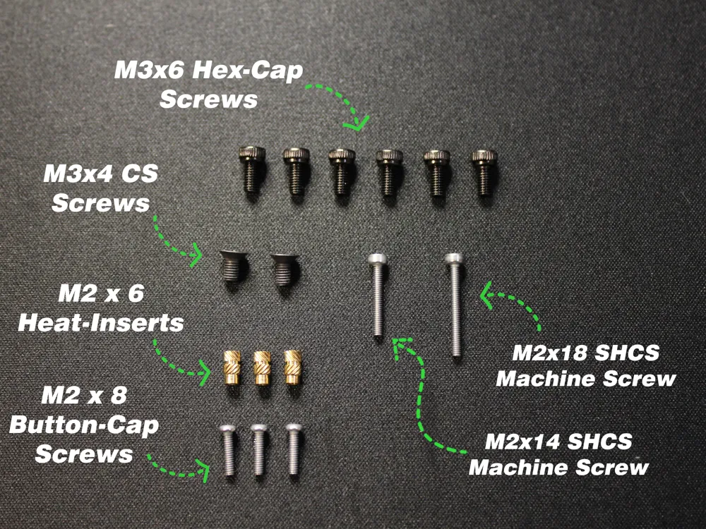
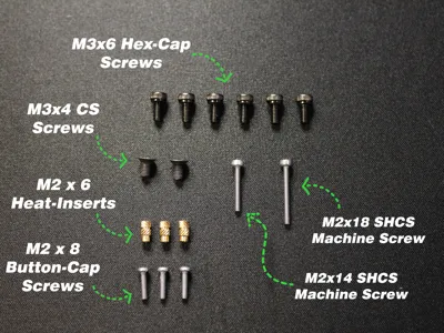
Once you have printed the model, start by installing the ESP32. You can use (2x) or (4x) M3x6mm Screws to secure the ESP32.
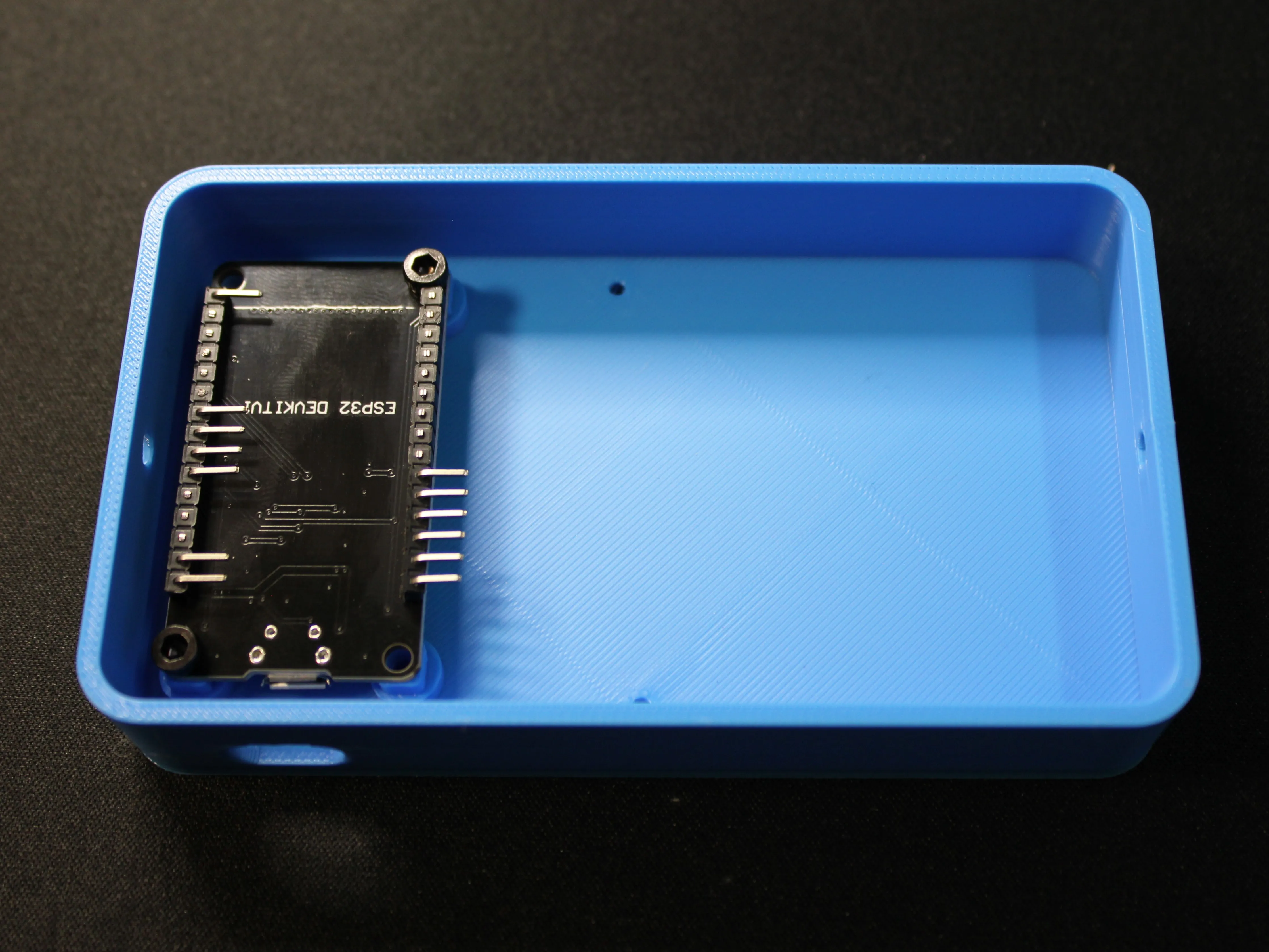
Step 2:
If your screen is equipped with headers, remove them.
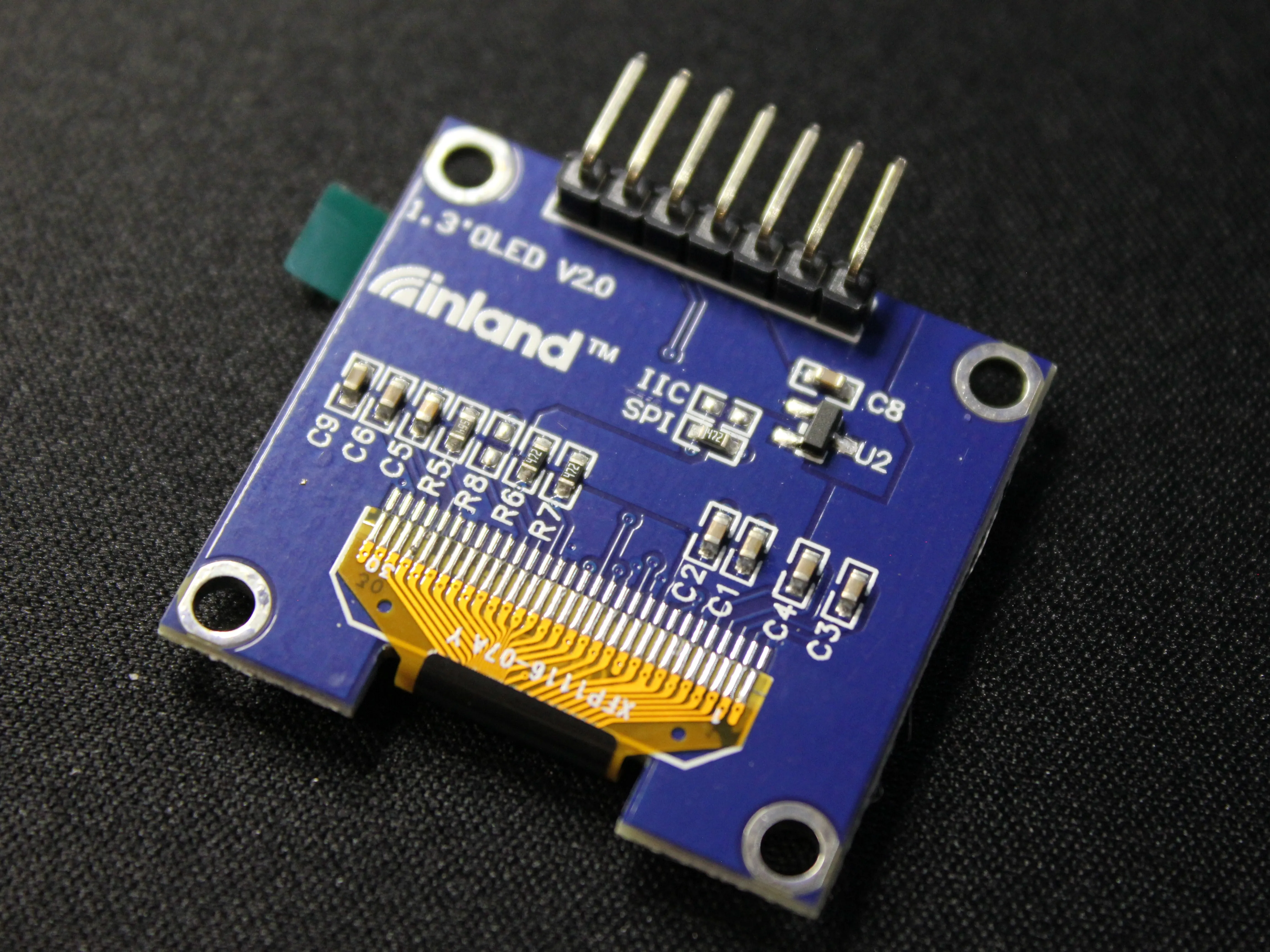
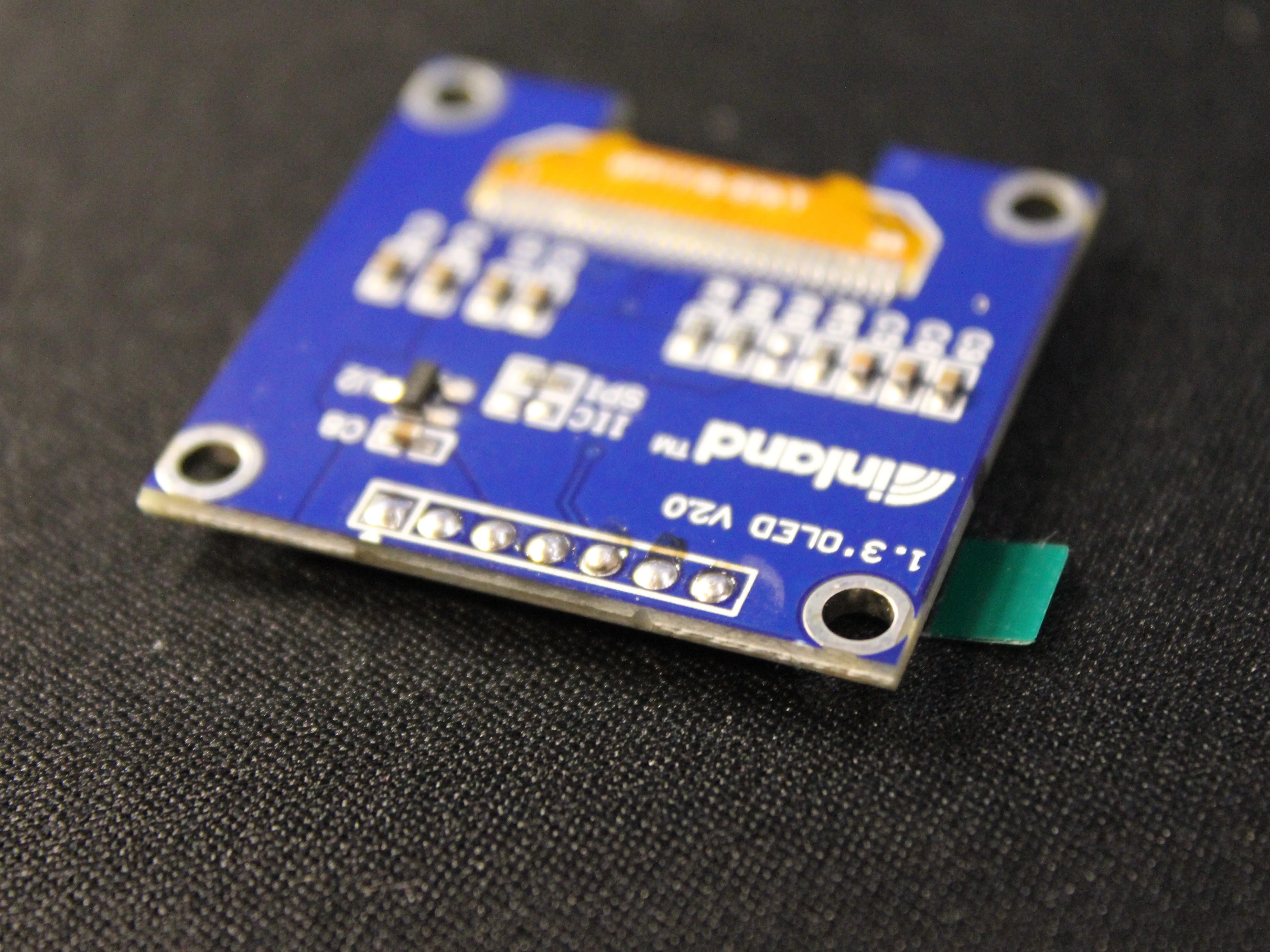
Step 3:
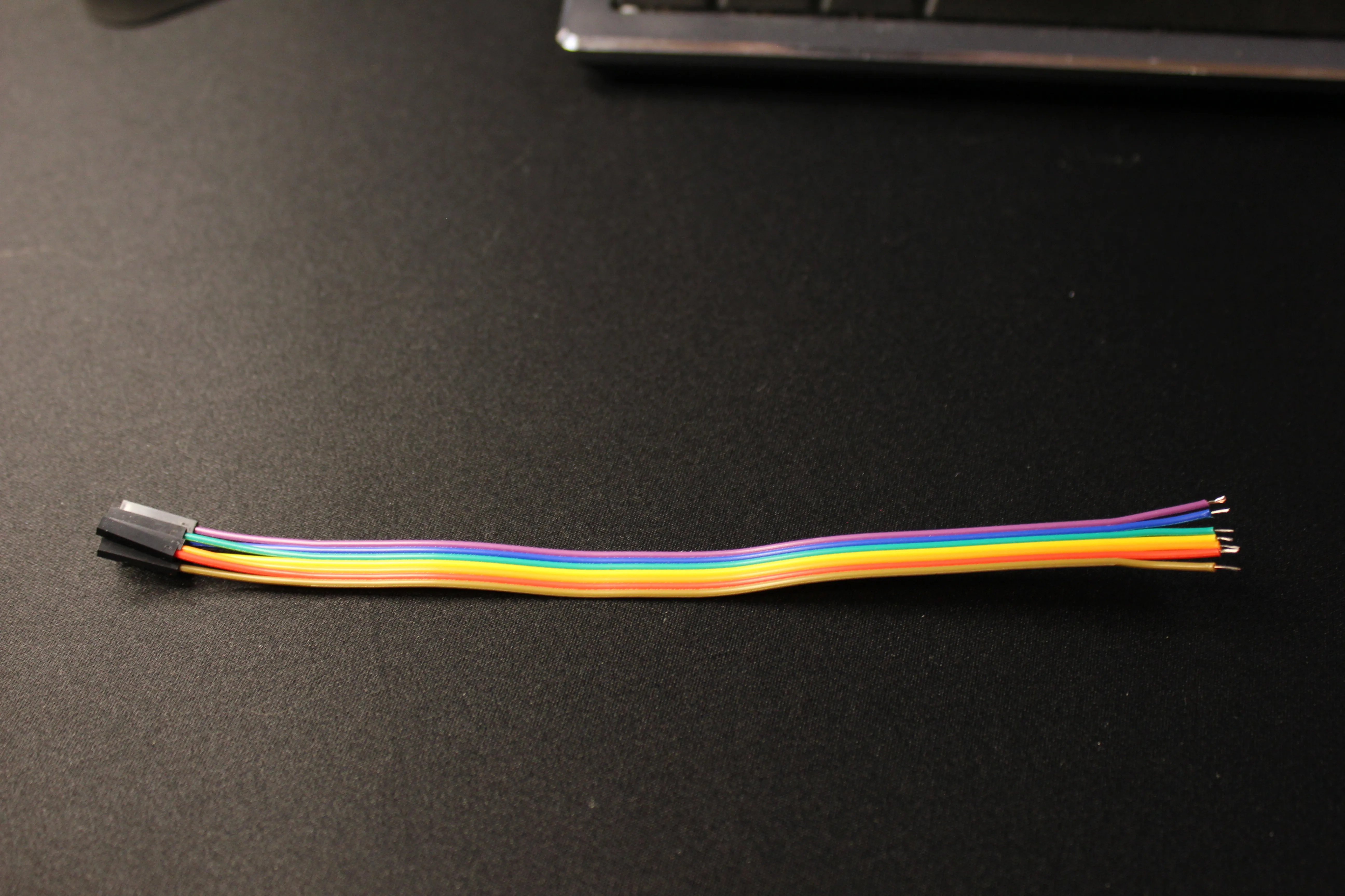
Take 7 jumper wires and cut off one side of the connectors - I recommend leaving ~ 6 inches of wire to work with; Longer wire is not better in this case
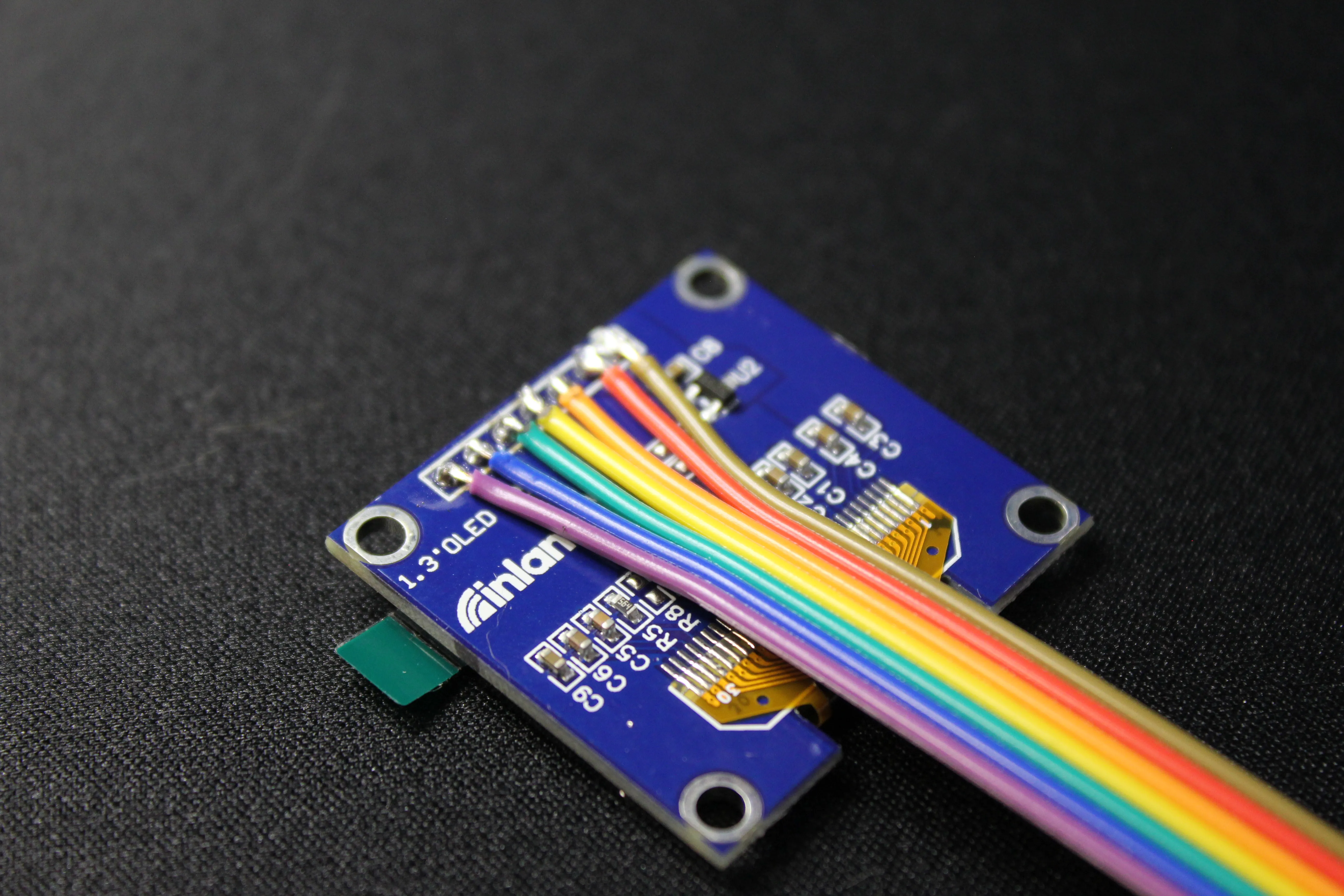
Strip and Tin the ends of the wires and solder them into place, making sure all contacts are clean and well placed
The wires should be pointing away from the solder pads
Step 4:
Install the M2x6 heat inserts in the Keypad Mount
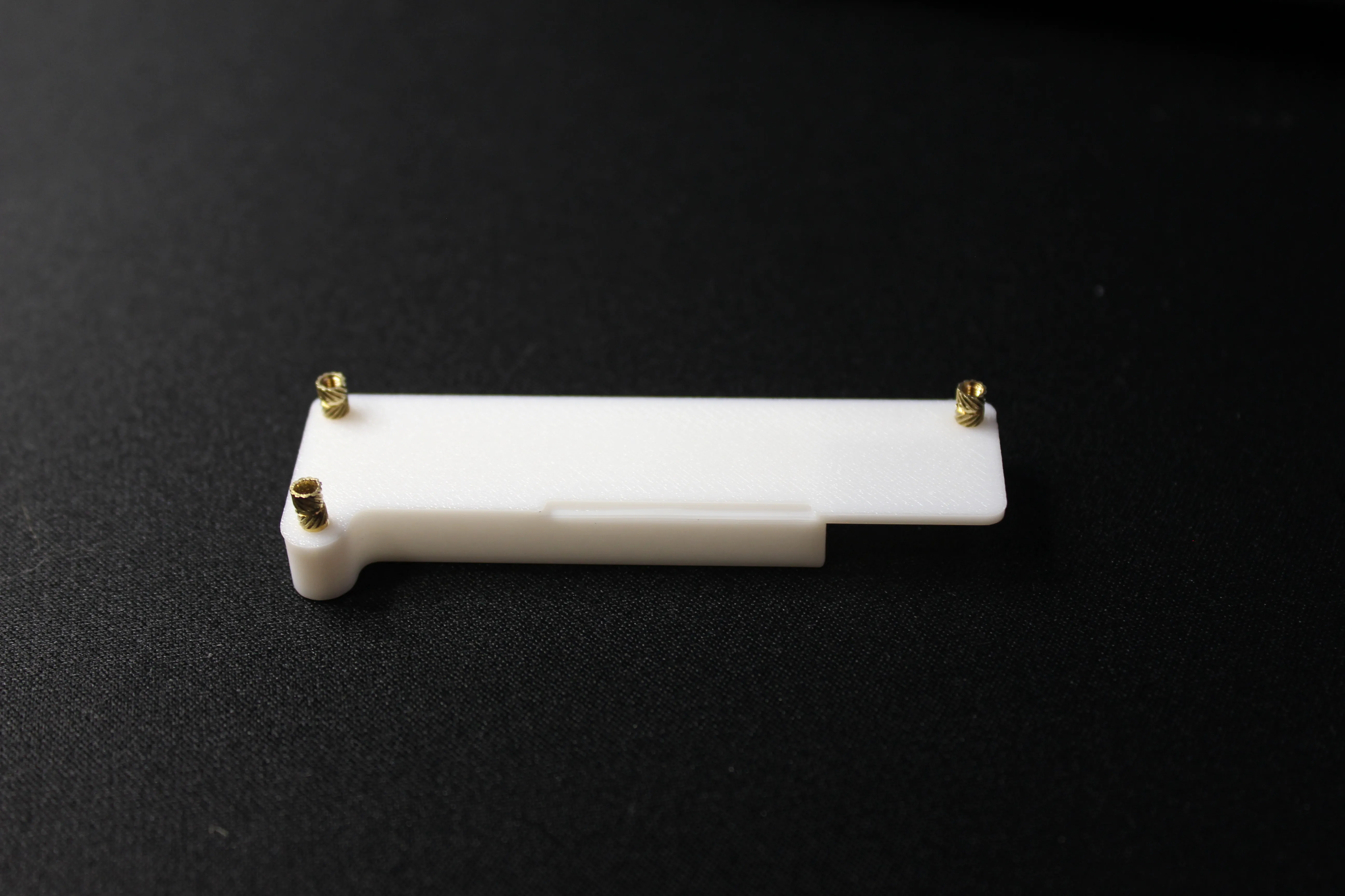
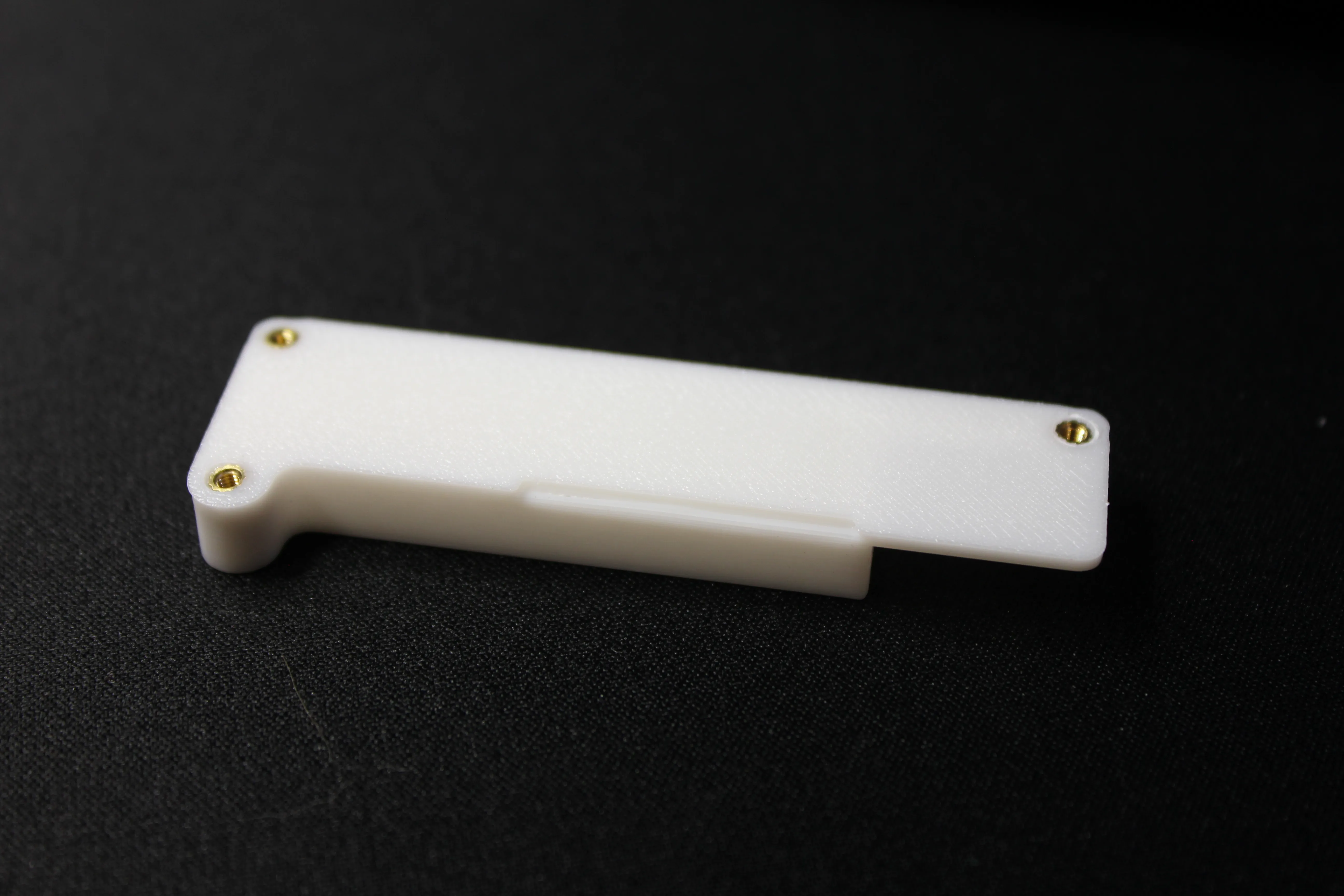
Step 5:
You'll either need to drill a small hole in the 1x4 membrane keypad, or cut off ~6mm of material from the side of the keypad to clear the screw.
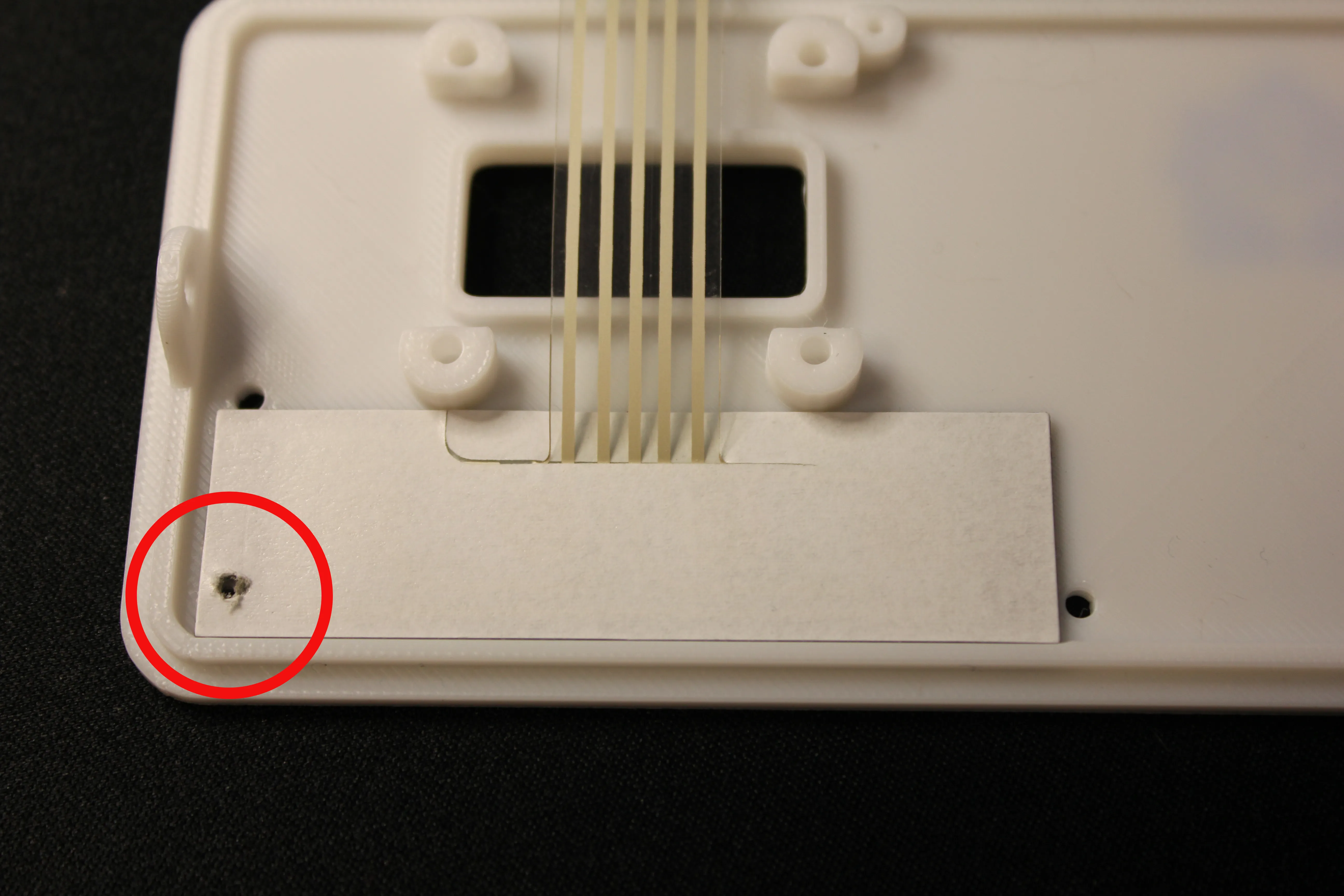
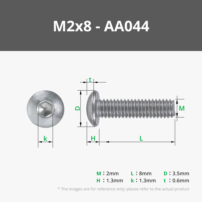
With that done, you can install the 1x4 Membrane Keypad using (3x) M2x8mm Button Cap Screws. These only need to be finger-tight; be careful not to overtighten.
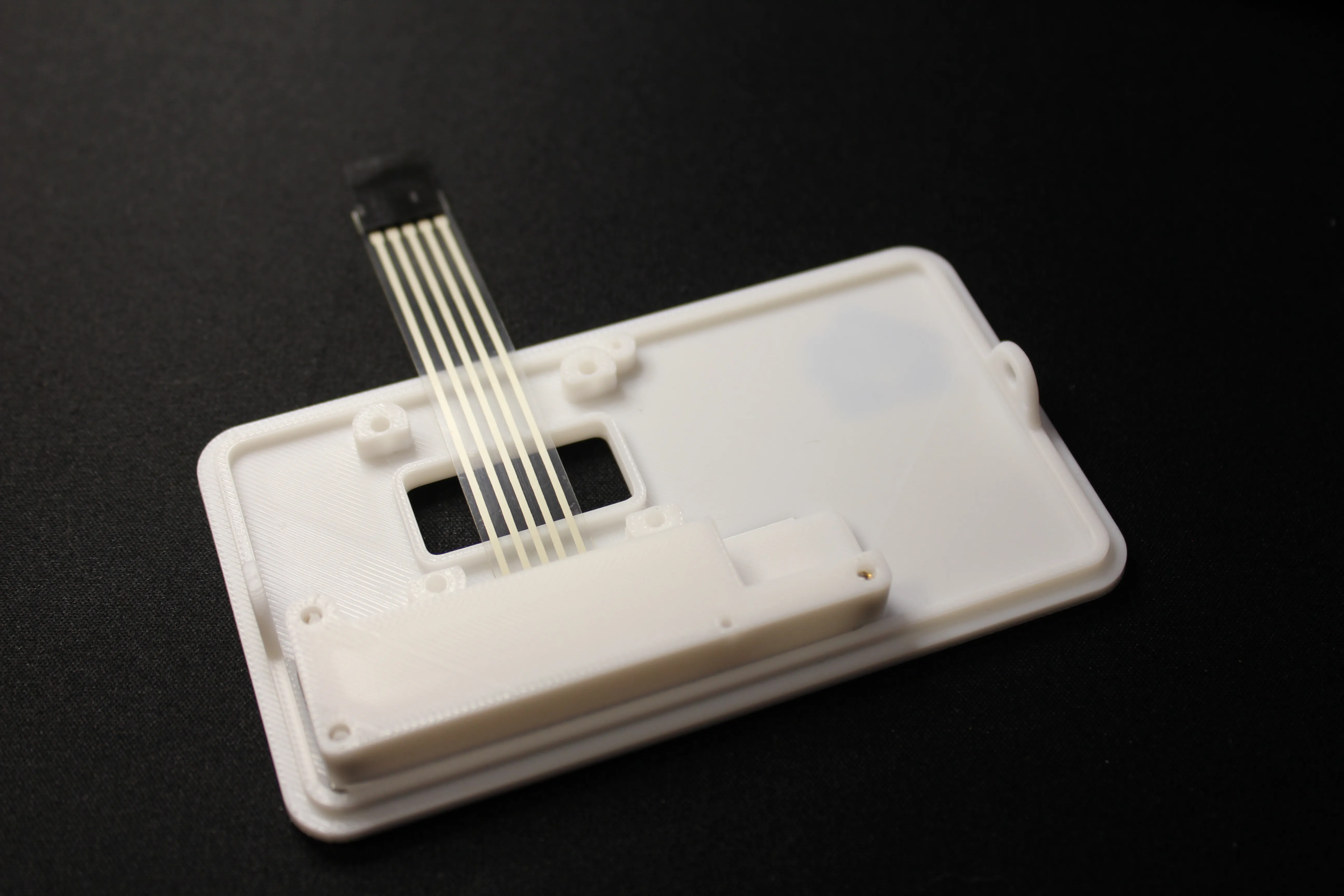
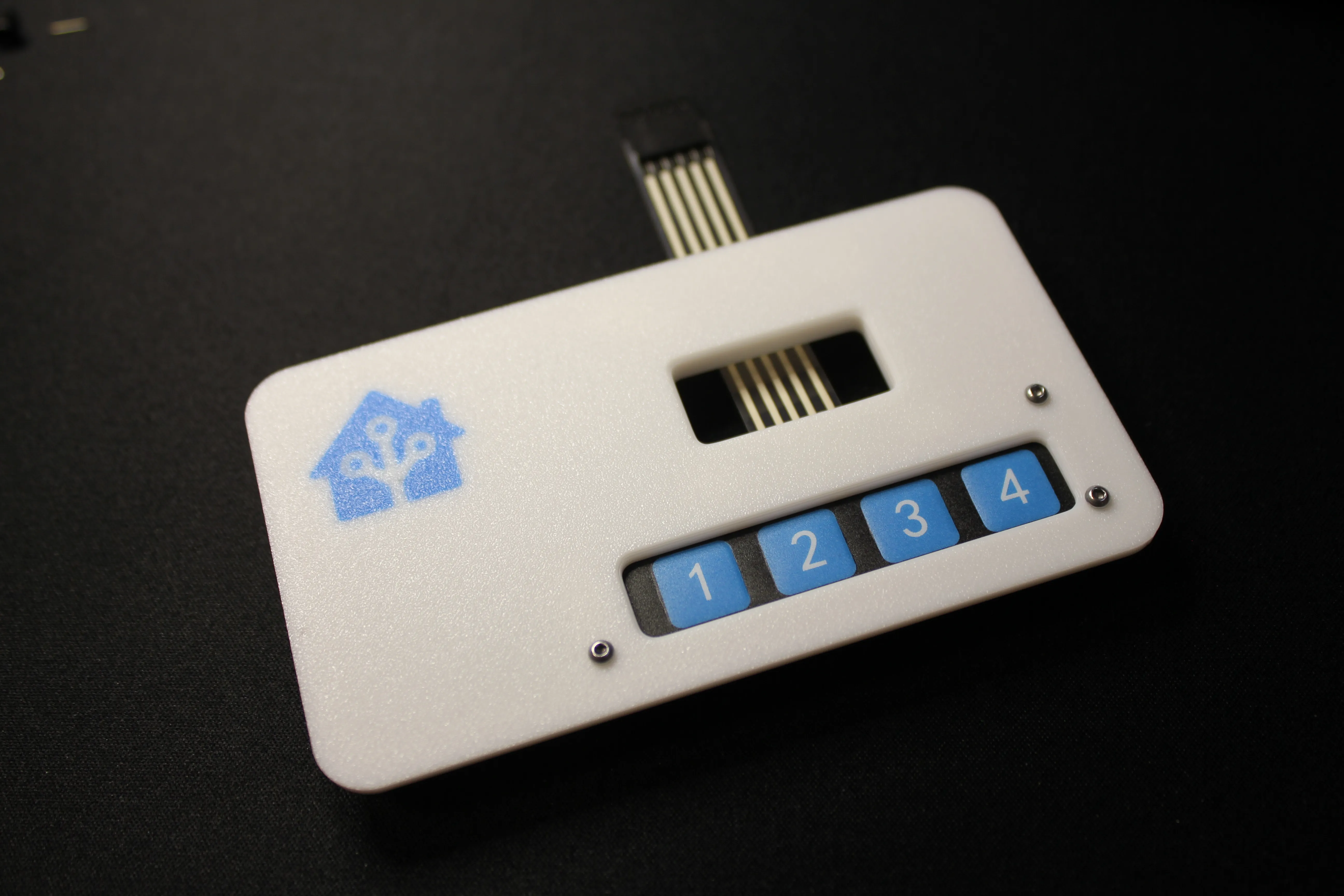
Step 6:
You can now install the OLED Screen using (4x) M3x6mm Hex Cap Screws. I recommend pre-threading these screws before final installation.
SCREEN ORIENTATION MATTERS! Make sure the screen is installed the right way.
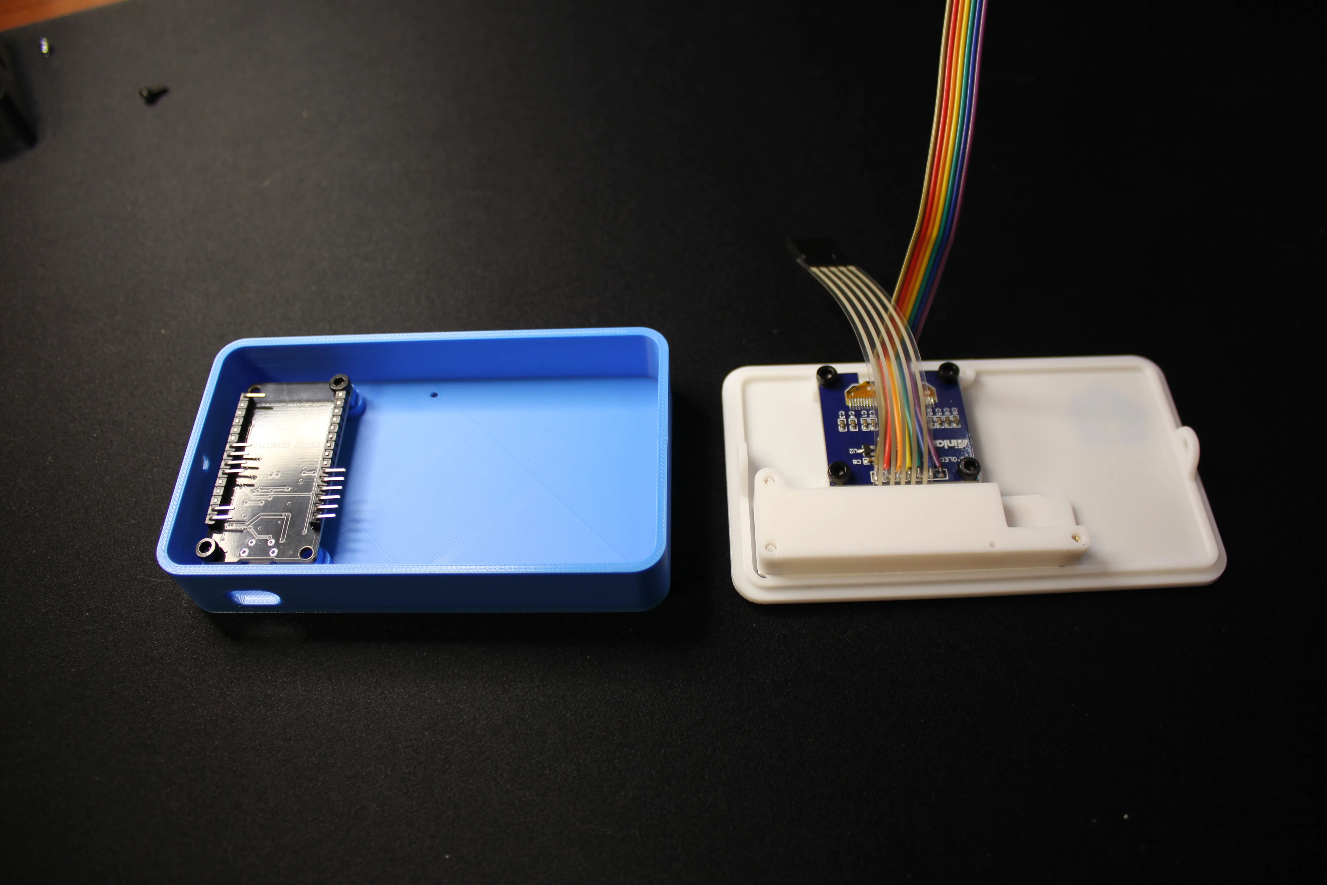
Step 7:
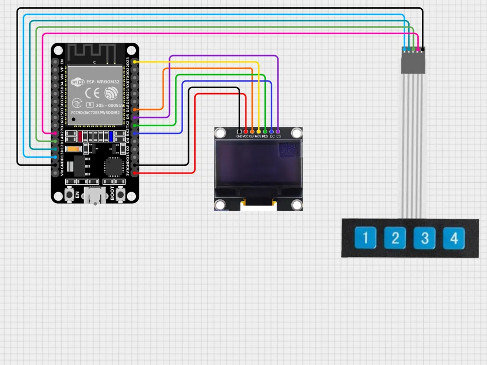
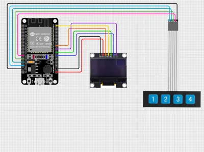
Time to wire this thing up! To help with this, I've included a link to an online interactive wiring diagram! Link HERE
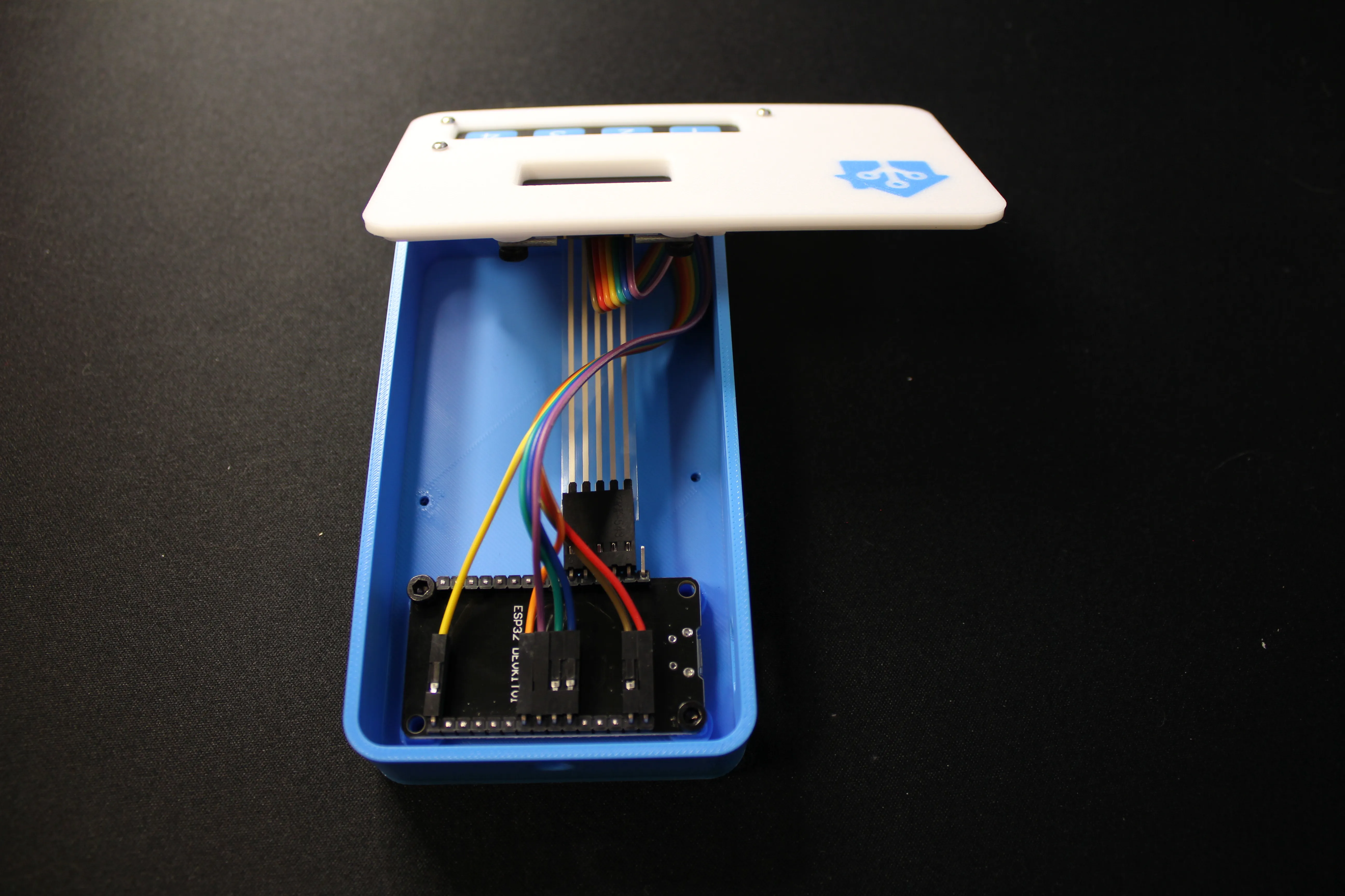
Some Wiring Notes:
- Depending on your specific 1x4 Membrane Keypad, the common ground may be pin 1 or pin 5. Verify the pinout of your model
- Some hot glue can really help hold down the wires and prevent them from coming loose
Step 8:
Almost Done!
Now that the wiring is complete, you can shut the case and install the (2x) countersunk M3x5mm Screws on the sides of the case; Because these thread directly into the plastic, be careful not to overtighten.
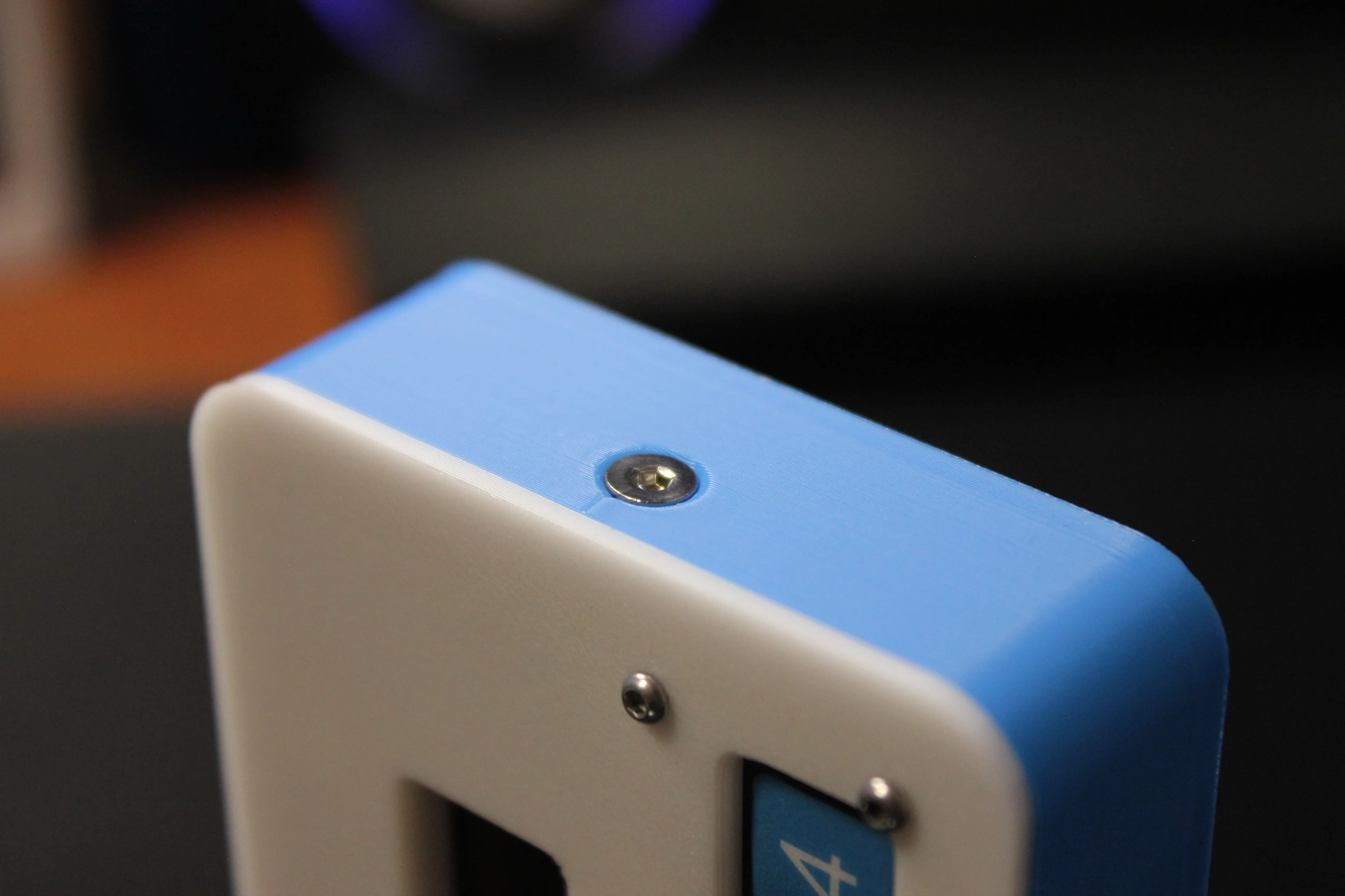
Step 9:
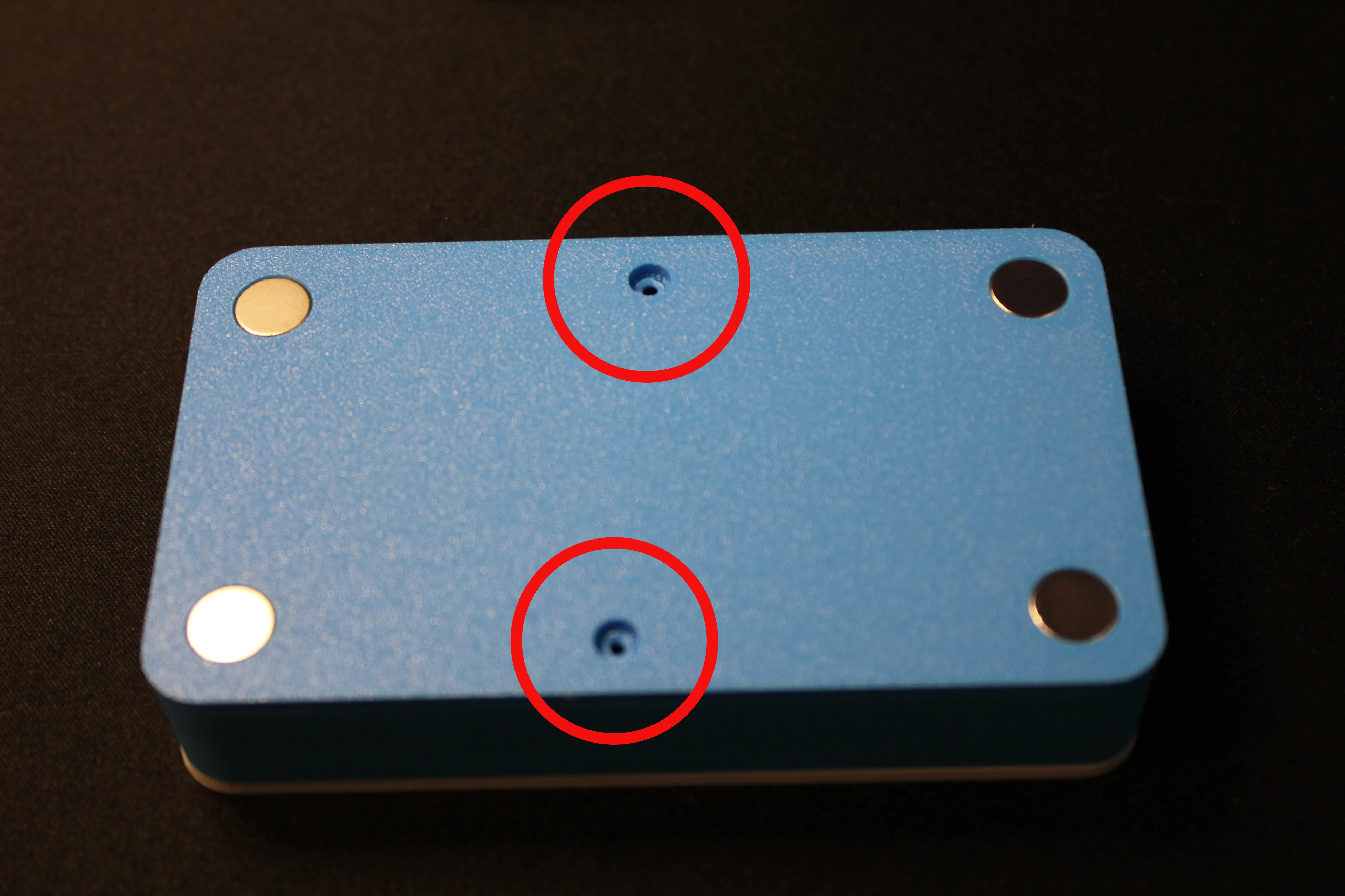
There are 2 small support surfaces on the backside of the case - remove these ( Circled in Red)
You can now install the 10x2 magnets. I've designed these to be push-fit, but feel free to use a little glue if you'd like.
Step 10 - optional but recommended:
If you didn't cut your wiring short enough, there's a chance it can push on the front cover, creating a small gap.
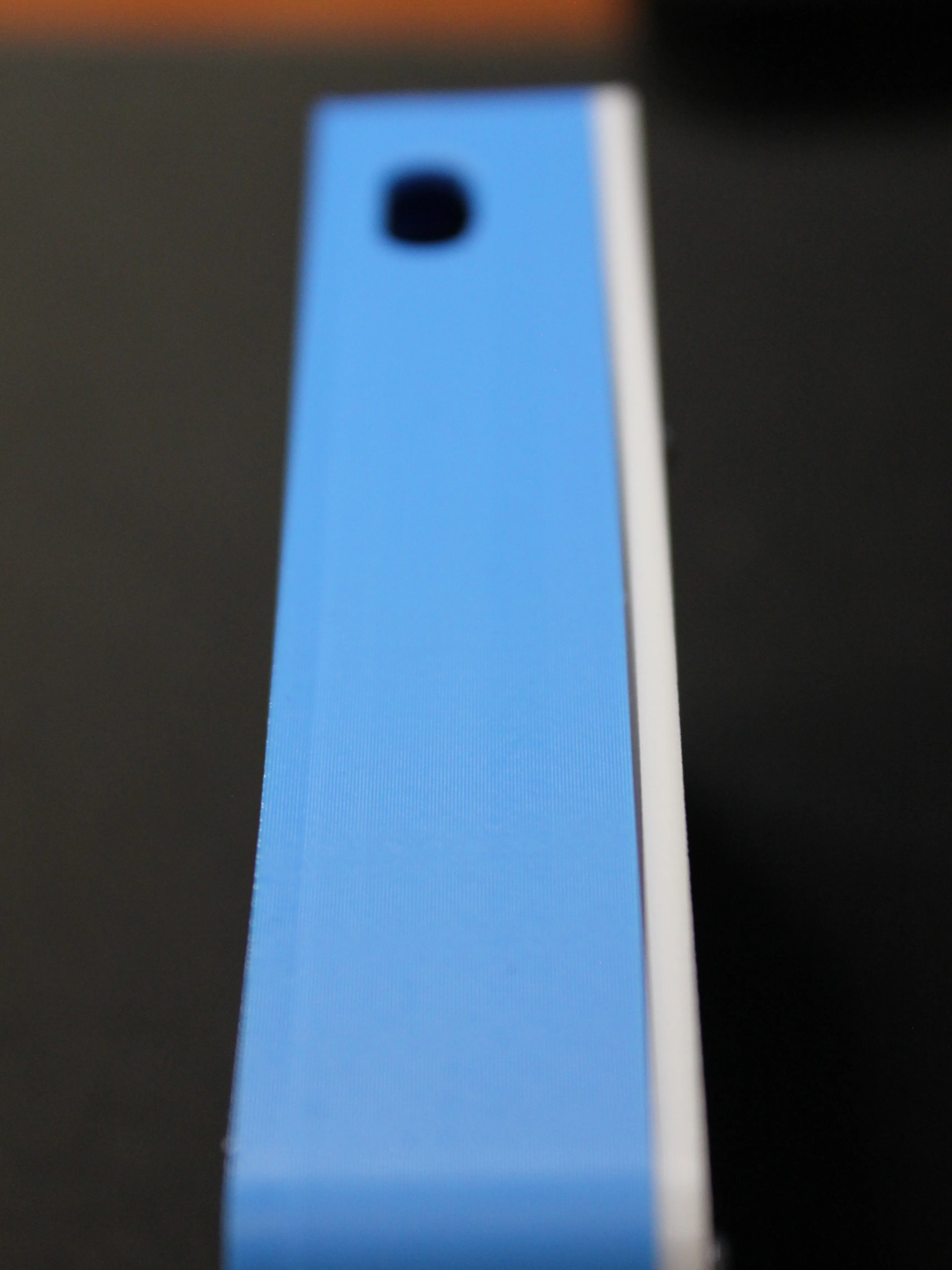
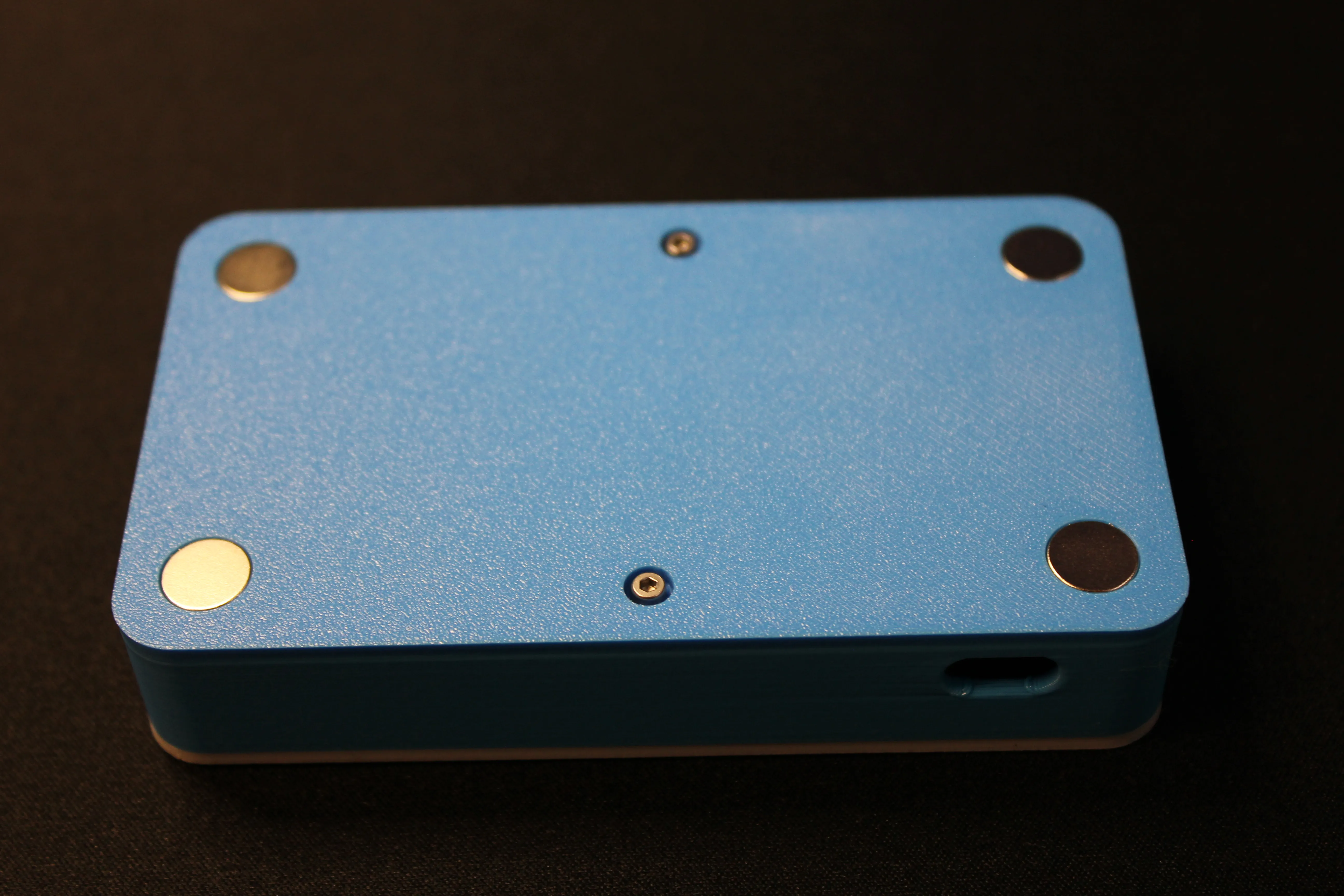
The two small screws on the back of the case can help pull the front cover back into alignment, eliminating the gap altogether.
The M2x14mm goes towards the top of the case and the M2x18mm screw goes towards the bottom
All Done!
Step back and admire your work!
YAML:
captive_portal:
# SPI bus configuration for the OLED screen
spi:
clk_pin: GPIO18 # Clock pin for SPI communication
mosi_pin: GPIO23 # Data pin (Master Out, Slave In)
# Loads a font from Google Fonts (Roboto, size 16) to use on the screen
font:
- file: "gfonts://Roboto"
id: font1
size: 16
# OLED display setup using SPI connection
display:
- platform: ssd1306_spi
model: "SH1106 128x64" # 1.3" OLED display with SH1106 controller
cs_pin: GPIO5 # Chip select pin for SPI
dc_pin: GPIO16 # Data/Command pin
reset_pin: GPIO17 # Reset pin for the display
id: oled_display
rotation: 180 # Flips the screen upside down because of how it's mounted
update_interval: 1s # Refresh display once per second
# Pages are different views you can show on the screen
pages:
- id: page_main
lambda: |- # This is the main screen shown by default
it.print(6, -2, id(font1), "1: Scene 1");
it.print(6, 12, id(font1), "2: Scene 2");
it.print(6, 26, id(font1), "3: Scene 3");
it.print(6, 40, id(font1), "4: Scene 4 ");
# These are the pages shown temporarily after a button press
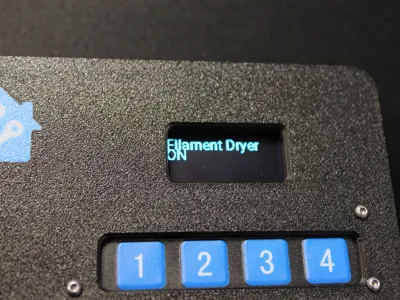
- id: page1
lambda: |-
it.print(0, 0, id(font1), "Scene 1 triggered");
- id: page2
lambda: |-
it.print(0, 0, id(font1), "Scene 2 triggered");
- id: page3
lambda: |-
it.print(0, 0, id(font1), "Scene 3 triggered");
- id: page4
lambda: |-
it.print(0, 0, id(font1), "Scene 4 triggered");
# Button inputs (binary sensors) from the membrane keypad
binary_sensor:
# Button 1 triggers Scene 1
- platform: gpio
pin:
number: GPIO12 #What GPIO Pin the button is assigned to
mode: INPUT_PULLUP # Enables internal pull-up resistor
inverted: true # Button connects to GND, so logic is flipped
name: "Keypad Button 1"
internal: true # This hides the button from Home Assistant UI
on_press:
then:
- logger.log: "Scene 1 activated" # Logs to ESPHome console
- homeassistant.service:
service: scene.turn_on
data:
entity_id: scene.scene_1 # Triggers Home Assistant scene
- display.page.show: page1 # Show confirmation screen
- delay: 5s # Wait 5 seconds
- display.page.show: page_main # Return to main screen
# Button 2 triggers Scene 2
- platform: gpio
pin:
number: GPIO13
mode: INPUT_PULLUP
inverted: true
name: "Keypad Button 2"
internal: true
on_press:
then:
- logger.log: "Scene 2 activated"
- homeassistant.service:
service: scene.turn_on
data:
entity_id: scene.scene_2
- display.page.show: page2
- delay: 5s
- display.page.show: page_main
# Button 3 triggers Scene 3
- platform: gpio
pin:
number: GPIO27
mode: INPUT_PULLUP
inverted: true
name: "Keypad Button 3"
internal: true
on_press:
then:
- logger.log: "Scene 3 activated"
- homeassistant.service:
service: scene.turn_on
data:
entity_id: scene.scene_3
- display.page.show: page3
- delay: 5s
- display.page.show: page_main
# Button 4 triggers Scene 4
- platform: gpio
pin:
number: GPIO14
mode: INPUT_PULLUP
inverted: true
name: "Keypad Button 4"
internal: true
on_press:
then:
- logger.log: "Scene 4 activated"
- homeassistant.service:
service: scene.turn_on
data:
entity_id: scene.scene_4
- display.page.show: page4
- delay: 5s
- display.page.show: page_main
License

You shall not share, sub-license, sell, rent, host, transfer, or distribute in any way the digital or 3D printed versions of this object, nor any other derivative work of this object in its digital or physical format (including - but not limited to - remixes of this object, and hosting on other digital platforms). The objects may not be used without permission in any way whatsoever in which you charge money, or collect fees.


Comment & Rating (38)