NDT ZFP UT Steel Plate Inspection

Print Profile(0)
Description
My first self-designed creation.
And ironically, for work… Well…
Esteemed ZFP inspectors and aspiring inspectors.
This design arose from necessity and laziness. I have an aversion to kneeling work. I already have a piece of steel embedded in my knee.
And since my boss likes to attempt monetizing my intellectual property, and this project has been languishing in a drawer for ages, I decided to release the files.
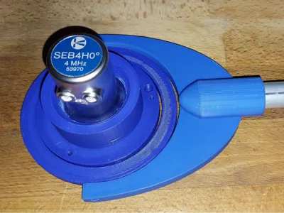
This is a quickly designed tool for inspecting steel plates for lamination using a SEB ultrasonic transducer, a standard watering can, and a handle. (In my case, I had two crutches lying around, so I repurposed one.)
In English: Lamination test.
The experienced UT inspector is familiar with DIN EN 10160:
Ultrasonic testing of steel flat products with a thickness equal to or greater than 6 mm (reflection method)
or
Ultrasonic testing of steel flat product of thickness equal to or greater than 6 mm (reflection method)
Quote from the standard:
The transducer may be guided either manually or in a continuously operating testing device.
End quote
Usually, so-called testing carriages costing several hundred euros are used. These are made of metal and typically incorporate so-called “underwater transducers.” This, however, is the luxury version. For companies that have little or no experience with such tests, purchasing such a carriage is not worthwhile. I was inspired to create this design by an old inspector who had a plastic sleeve turned for such occasions and had a clamp for the broomstick attached to the sleeve.
The design I am presenting here is a cost-effective alternative using a watering can and a standard SEB4 or other UT transducer with a large thread. An adapter for the MSEB will follow.
Printed in PETG, this is a preliminary version that will be improved when the opportunity arises.
BOM:
Countersunk screws:
3x M2 x 6mm (under the transducer mount. The 3 small holes visible in the transducer mount.)
1x M3 x 10mm (Locking screw for the UT transducer. Difficult to see because it’s black.)
2x M3 x 20mm (Fastening ring to the transducer mount)
2x M3 x 15mm (Fastening ring to the handle mount)
From here on, everything is optional if you don’t want to use a watering can.
1x OD 6mm brass hose connector (for example)

And depending on the person’s height and the length of the handle, a 6mm air hose. For water supply to the transducer mount.

Either via canister on a trolley, or use a water backpack.
These are available with up to 30L capacity. From boating supplies, for example.
But first, in this low-budget version:
First, wet the steel plate to be inspected using the watering can, then adjust the distance between the transducer and the steel plate. 1 mm of air under the transducer sole is sufficient. The capillary effect does the rest.
This can be done by gently rotating the transducer in the mount. Then tighten the adjustment screw to secure the transducer at the distance from the steel plate. Under the transducer mount (not currently visible) are 3x 3mm countersunk screws that rest on the steel plate to prevent wear on the mount and the transducer sole.
Then adjust your ultrasonic device and start testing. You don’t need to use a grid. It’s also possible, as with the “cutters” in grain harvesting. The main thing is that you cover the inspection area and perform the edge zone inspection properly.
In the near future, I will probably design a trolley to round things off. Preferably with the standard 100 and 200 mm wheel spacing. A feed for a 6mm hose to eliminate the watering can is already integrated. I would melt the hose connector in from the top there.
Suggestions are welcome, and this design is free for all, unless you want to make money selling the printed parts.
Or sell a sample or apply for a patent. That would at least be good for a laugh. The gimbal principle comes from antiquity after all.
Comment & Rating (7)