Elegoo PHECDA Limit Switches for X/Y Axis


Print Profile(1)

Description
Here I have created end stop switches for the X & Y axis for the Elegoo PHECDA. I have different versions which are all tested by me. I use these because I wanted my home in the back right corner because it always bothered me in the front when the whole slide is over the component.
However, there are a few small things to note in the settings for limit switch programming.
You can set it in the EEProm, but the built-in display always resets the basic value “3” for it, so I use my PHECDA completely without display, you don't need it anyway if you use Lightburn.
I use these parameters:
ATTENTION, these are only my values to give you an indication. Incorrect settings can lead to damage to the device.
$2=0
$3=4 ← ← ← ATTENTION, SEE ***
$4=0
$5=1
$6=0
$10=1
$13=0
$20=0
$21=1
$22=1
$23=3
For more context about these settings, please see the end of this document.
*** this value changes to 7 after every restart of the laser and is set by the display, to change this you can unplug the display
or you can set a Makro to Lightburn like “$3=4” so you can easy chance it after a restart / new start.
BACK ENDSTOP:
The rear end stop only needs 4x 6mm M4 screws, optionally only 2x if you leave out the left stop. Since I store my PHECDA on edge, I thought it would be a good idea to protect the switch from permanent full pressure.


X-SLIDE ENDSTOP
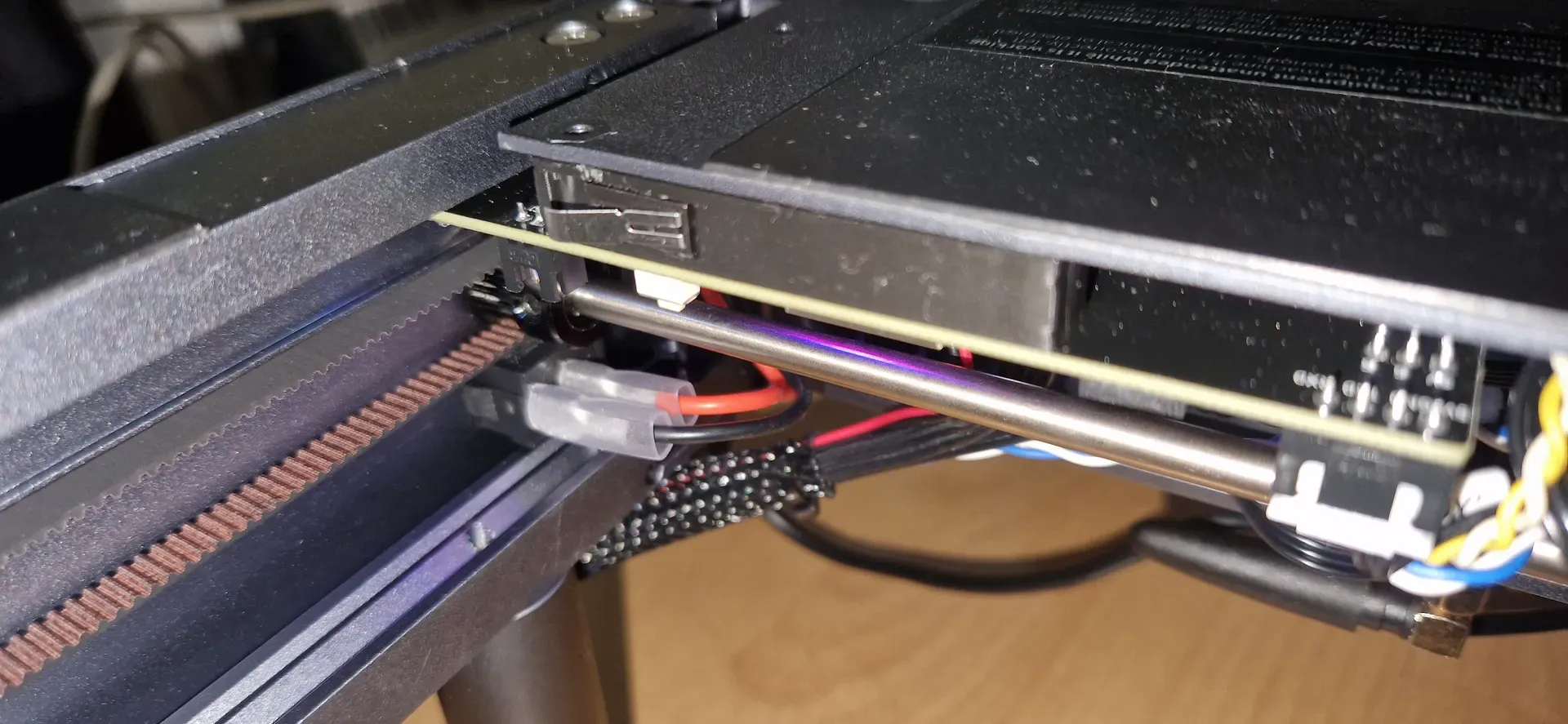
The X-switch sits directly on the Nema17 and is attached to the spaxers with which the motor is held.
The upper locking screw (picture 3) of the laser head is usually short enough as long as it is screwed in, however, if you load it loosely it can stick to the nema motor, so I advise you to remove it or shorten it by a few millimeters if you load it loosely.


FRONT ENDSTOP
I have also added my old former front switch holder as it is really tidy and matches the switches I use.
With this switch it is essential to ensure that the laser protection disk is inserted, otherwise it will not trigger.
If you still like this option better, you can help yourself by inserting a screw in the right place on the Y-slide that triggers the switch with its head and simply drill a hole in the plastic disk for the screw so that you can continue to remove the disk. Since there is an approximately 3cm large contact surface on this side.
I drill the small holes on the brackets with a 1.8mm drill and simply glue a piece of filament in there, let it dry and cut it flush.
I use the same switches for all positions, I made the cables myself. → → → Aliexpress

There will be some more addons for the PHECDA coming soon so please follow me.
And if you think what I'm doing is great, please give me a boost to encourage me to create more content.
Boost Me (for free)

Comment & Rating (0)