
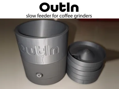
Slow feeder for coffee grinders
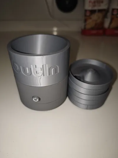
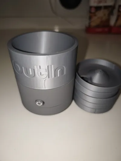
Print Profile(3)


Bill of Materials





- Neodimium magnet 3mm x 2mm N52 x 88: El numero minimo son 46
Description
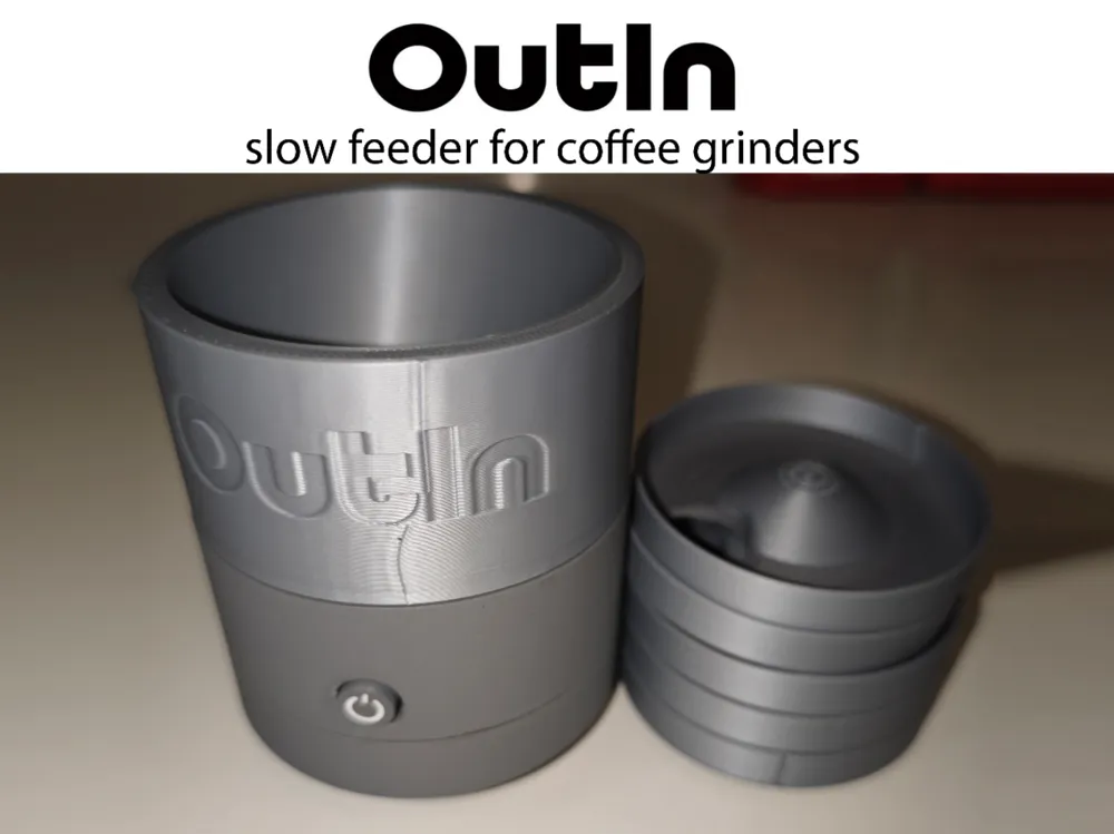
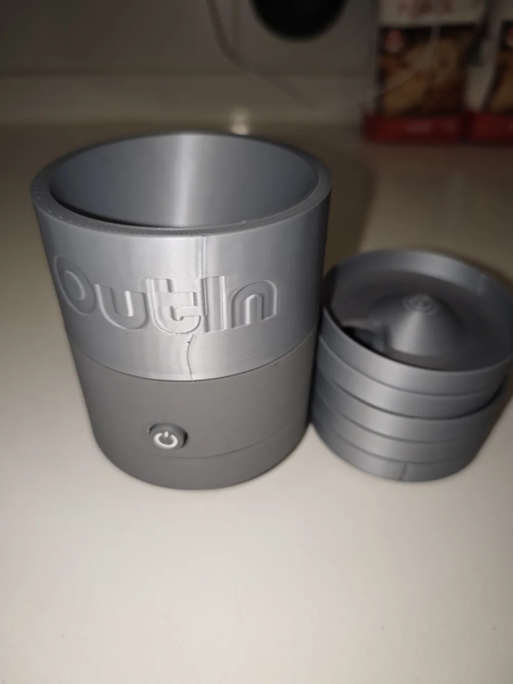
For coffee lovers, grinding is as important as the rest of the process. For this, we have the slow coffee bean doser for the grinder
The printing is very simple, everything is prepared so that not a large amount of supports is needed, the part fitting is calculated so that any printer can do it without problems
I bring you several printing profiles, with AMS for the white part of the button. Without AMS for those who do not have this option, so the button has the power symbol marked, and the most comfortable version to print, with AMS and using PETG as support filament, with 0 distance between parts, which provides a perfect finish on the parts that use support. In any case, it is not necessary to use this version as it is only a visual finish and does not affect the final operation at all, it is only aesthetic
For the motor, in my case I have used the double-shaft MakerWorld model, it was the only one I had available, which is still a bit tall and needs a potentiometer to adjust the rotation speed, so I had to cut the excess shaft. The option is to use the MakerWorld motor “N20 Single Shaft Worm Gear Motor (1PCS) - LA008”
ATTENTION - BEFORE ORDERING A MOTOR FROM ALIEXPRESS, CHECK THE MEASUREMENTS, SOME ARE VERY LARGE AND WILL NOT FIT INTO THE PRINTED MODEL
Thanks to Kamlotton's feedback, the correct model is the N20 from AliExpress
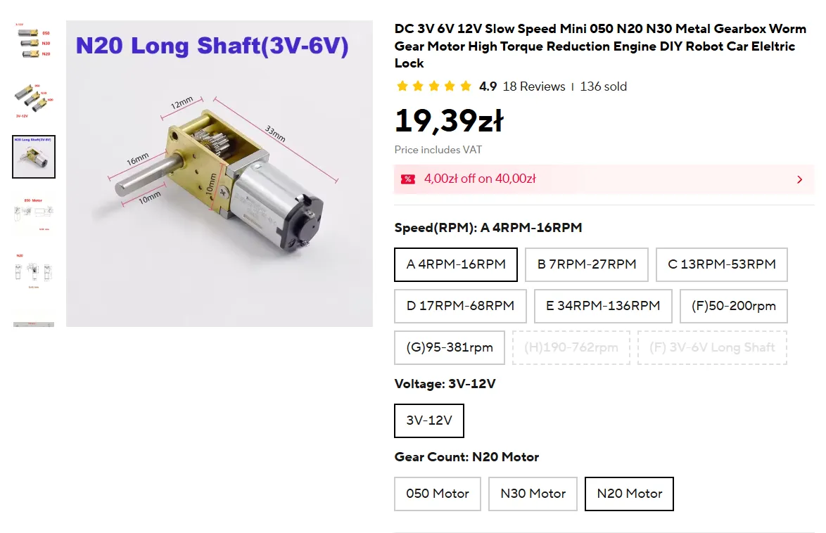
The wiring, if we start from the MakerWorld motor, forces us to make modifications, cut wires, battery terminals, and add a potentiometer to adjust the speed
Inside the motor compartment there is enough space to use all MakerWorld components, house cables, control boards, and potentiometers
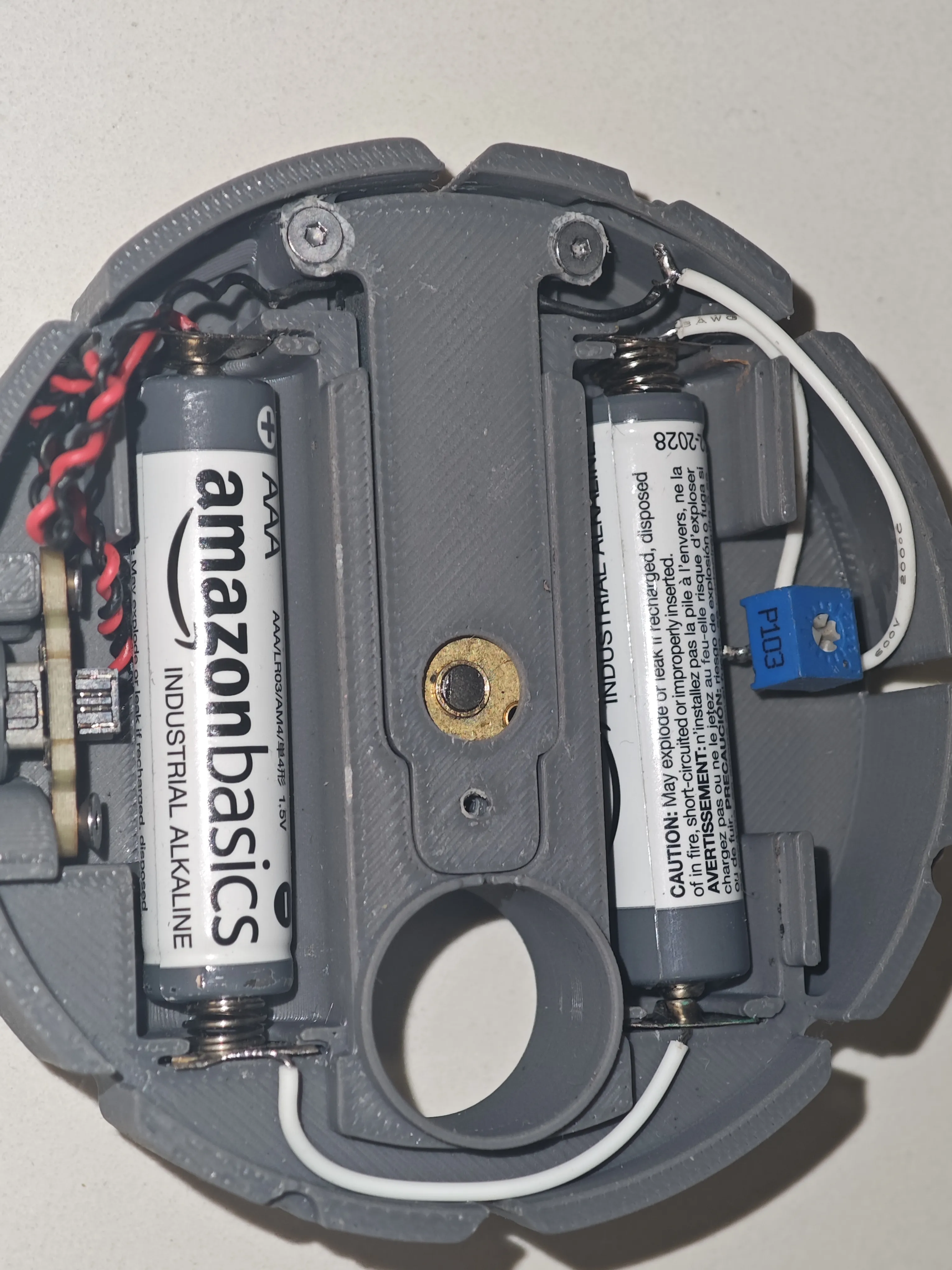
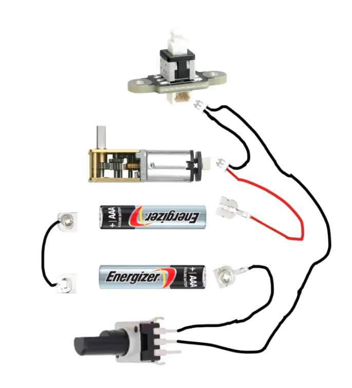
Regarding the wiring, it is very simple
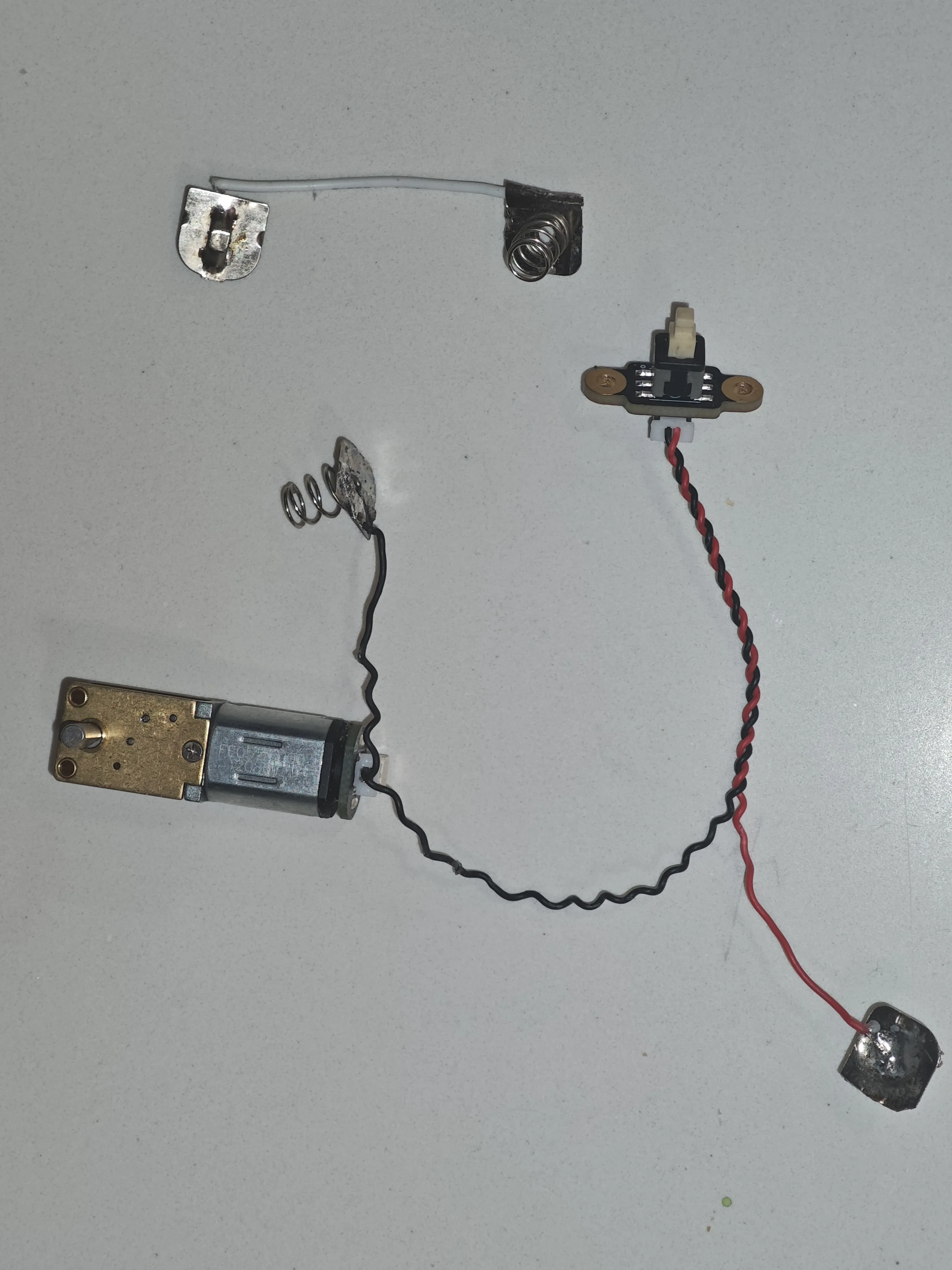
Once all the parts are printed, we begin assembly, it has no more complication than following the steps correctly
We start with the piece that houses the motor and batteries. We install the battery plates and the motor, routing all cables so they don't get caught under the motor
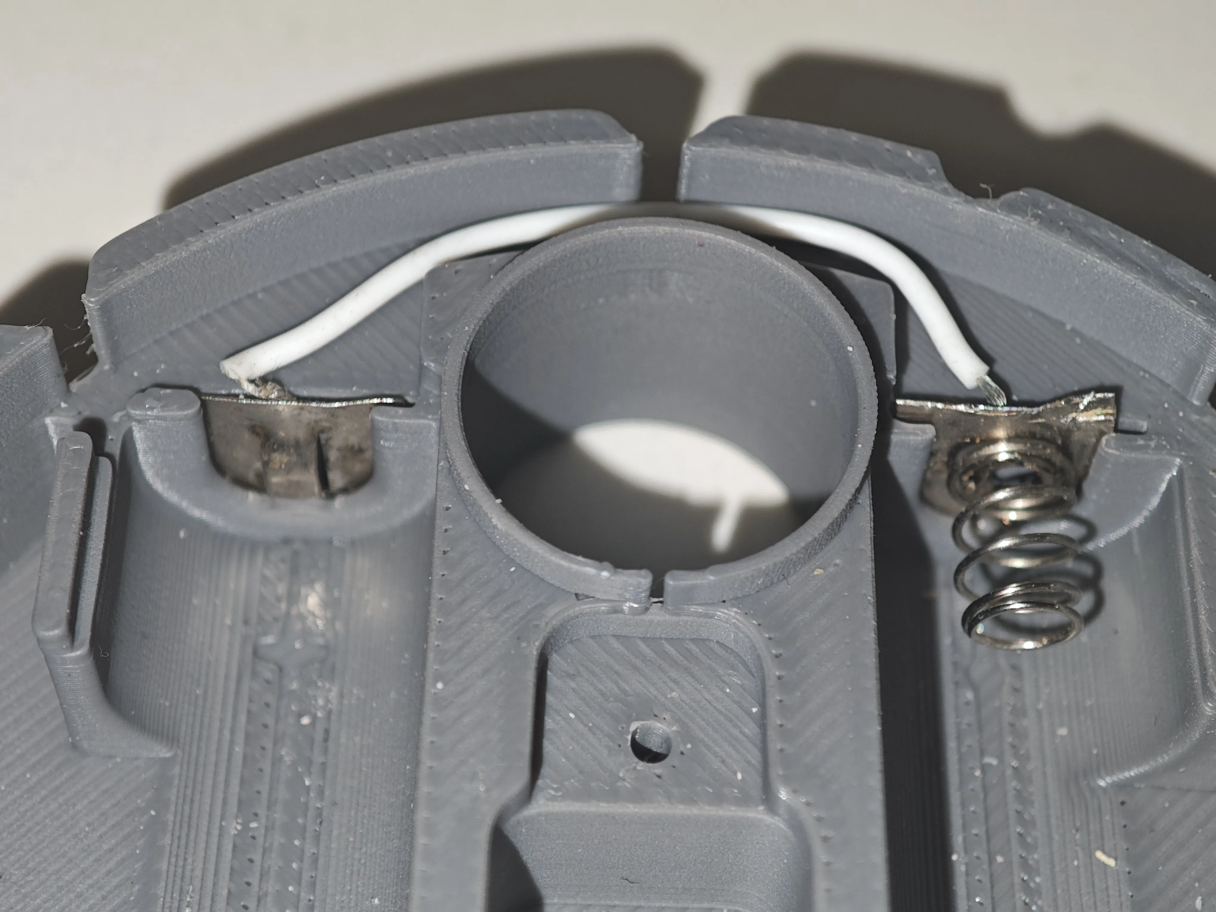
motor cable position so everything fits without problems
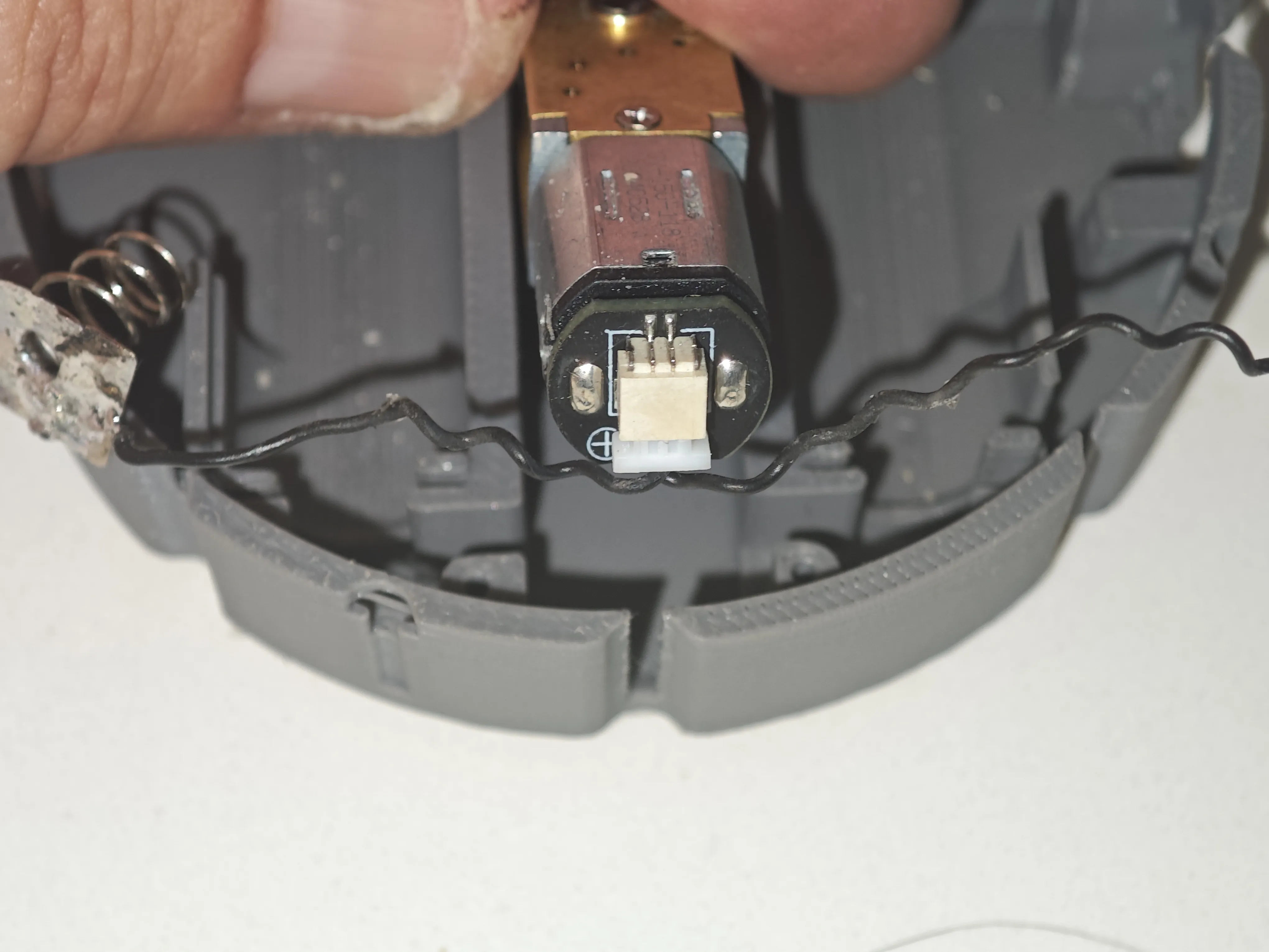
The other battery contact plates placed in their position
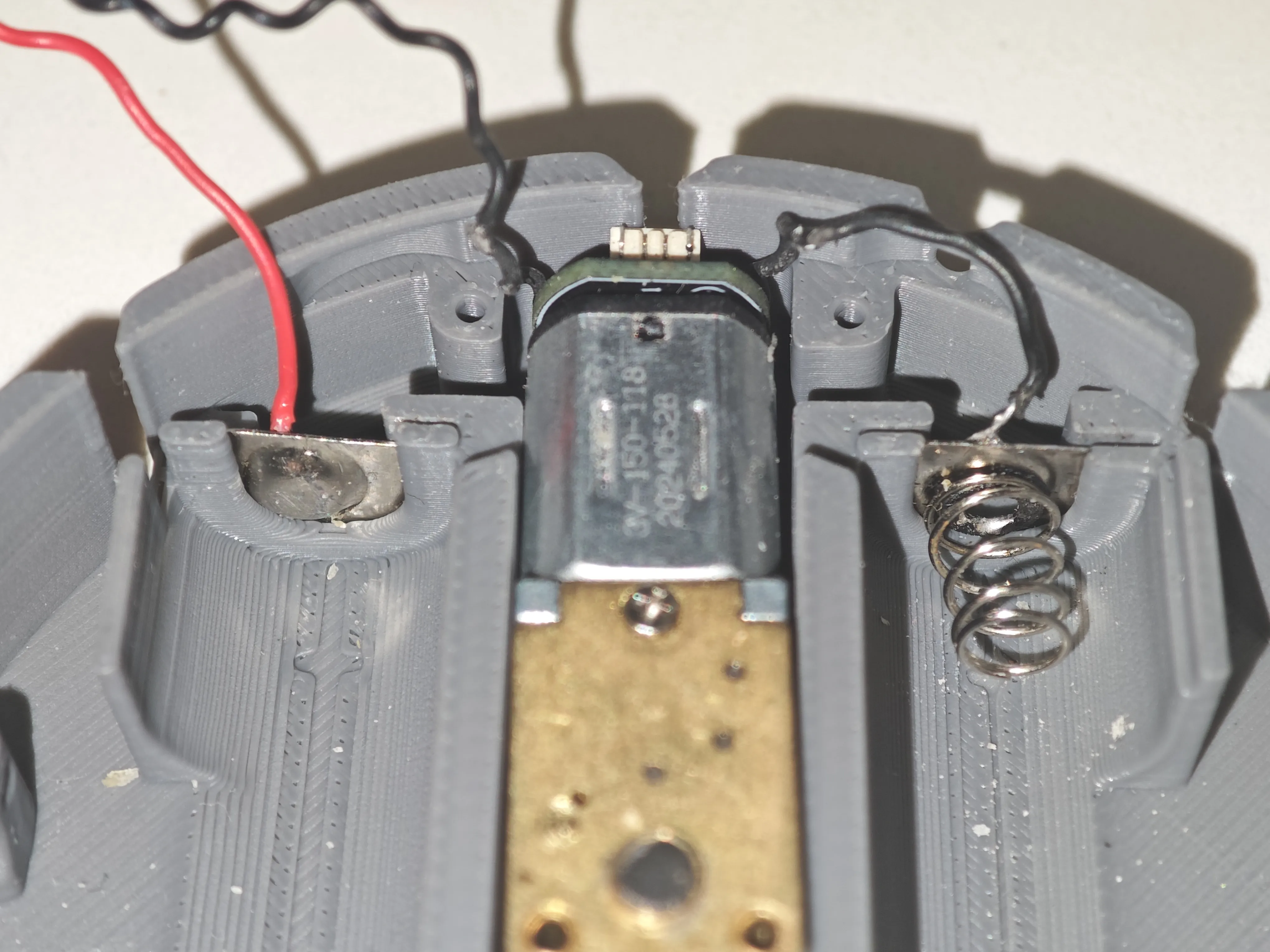
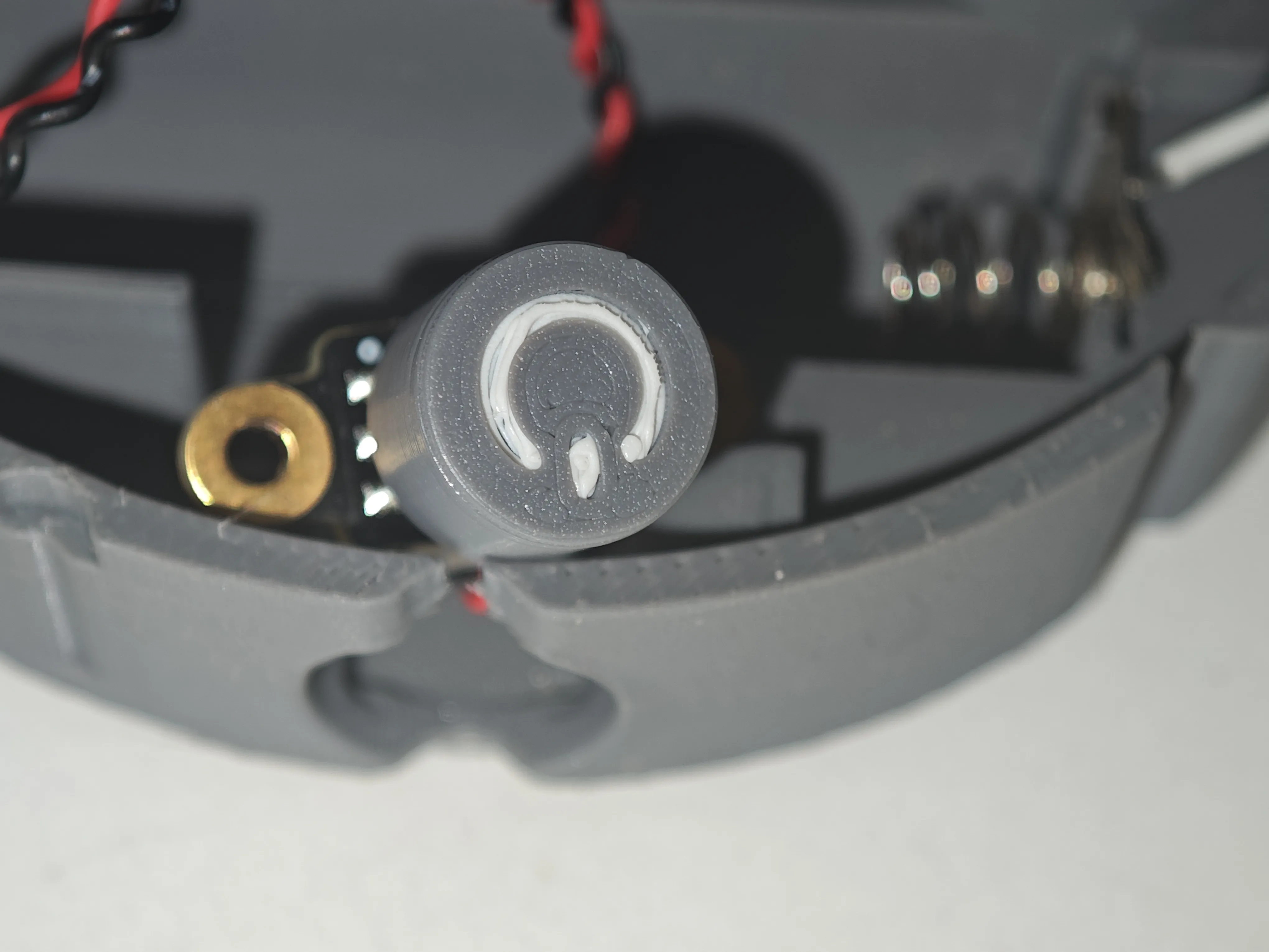
and the button which we do not yet place in its final position. The outer cover must be installed first
The final assembly without using a potentiometer is like this
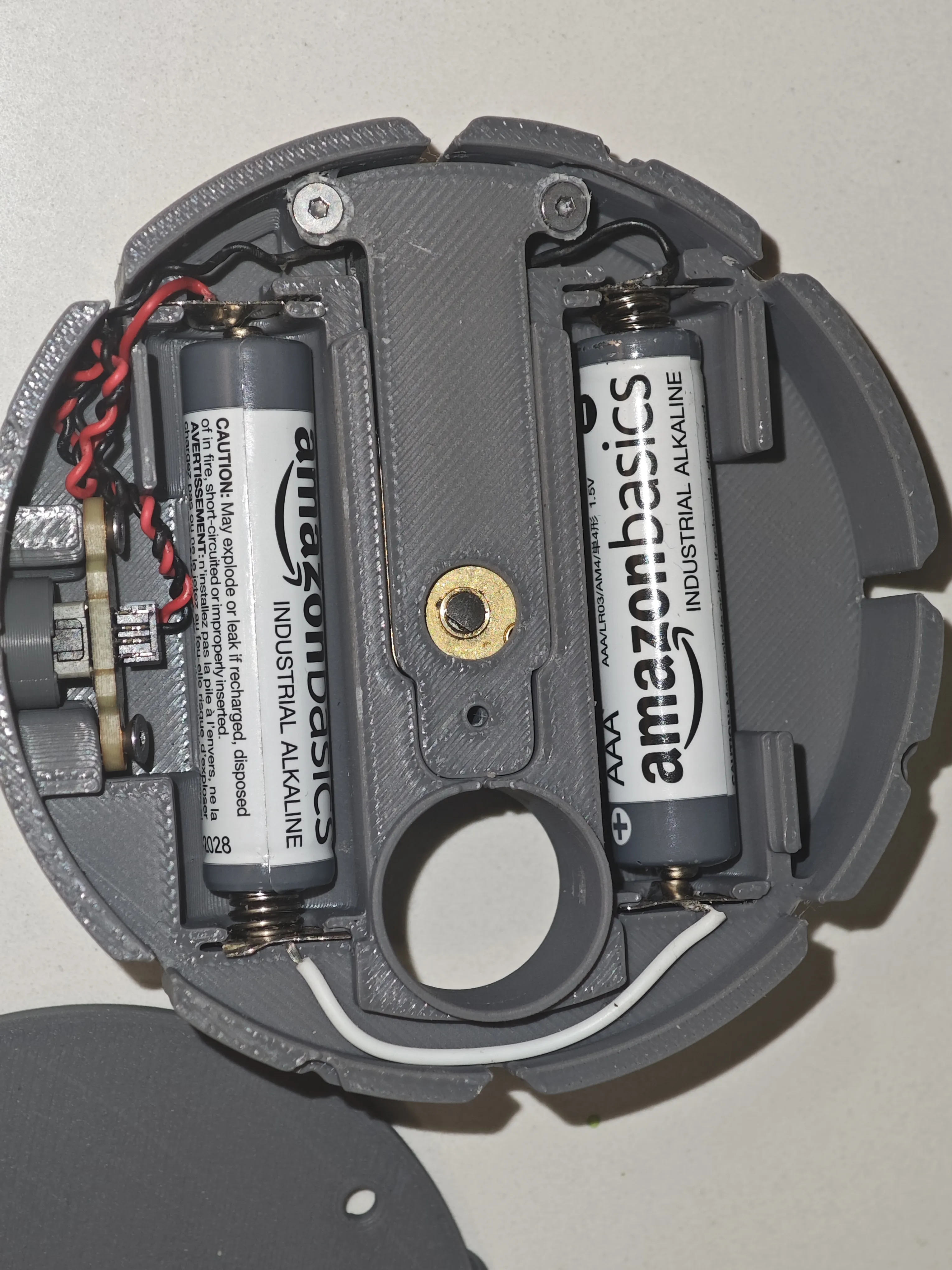
If we use a potentiometer, we attach it in the designated part with plenty of space. The MakerWorld potentiometer does not fit in the available space, you will have to get a compatible one, although the ideal is to use a low RPM motor
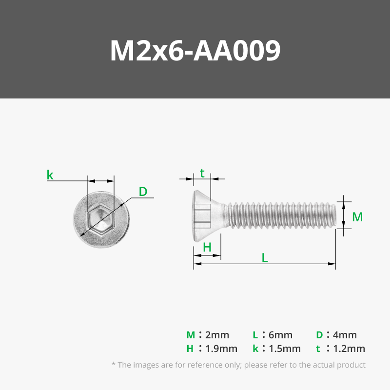
We place the motor holder so it doesn't move and install two M2 screws. We will use the same screws to fix the power button, two M2
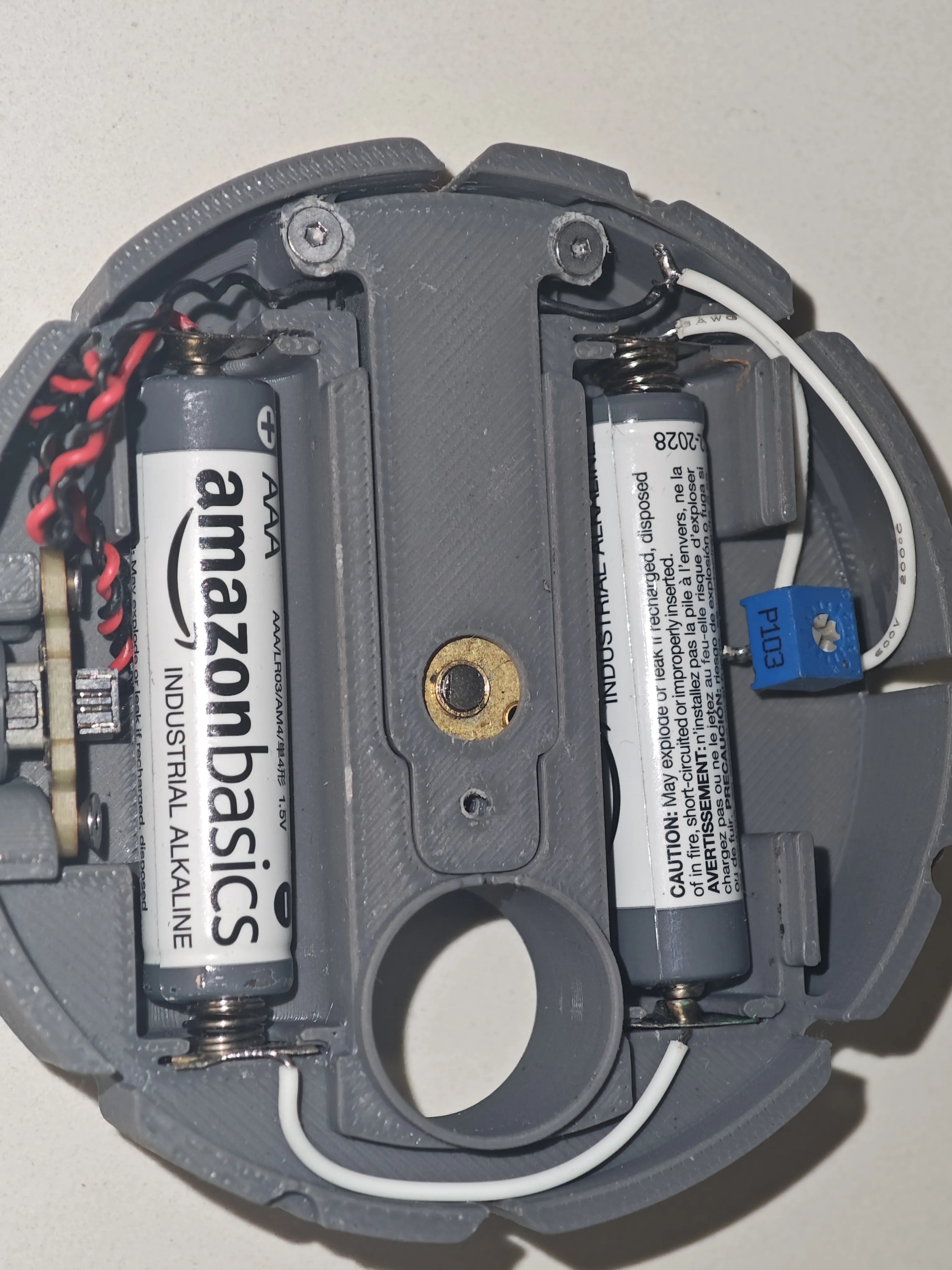
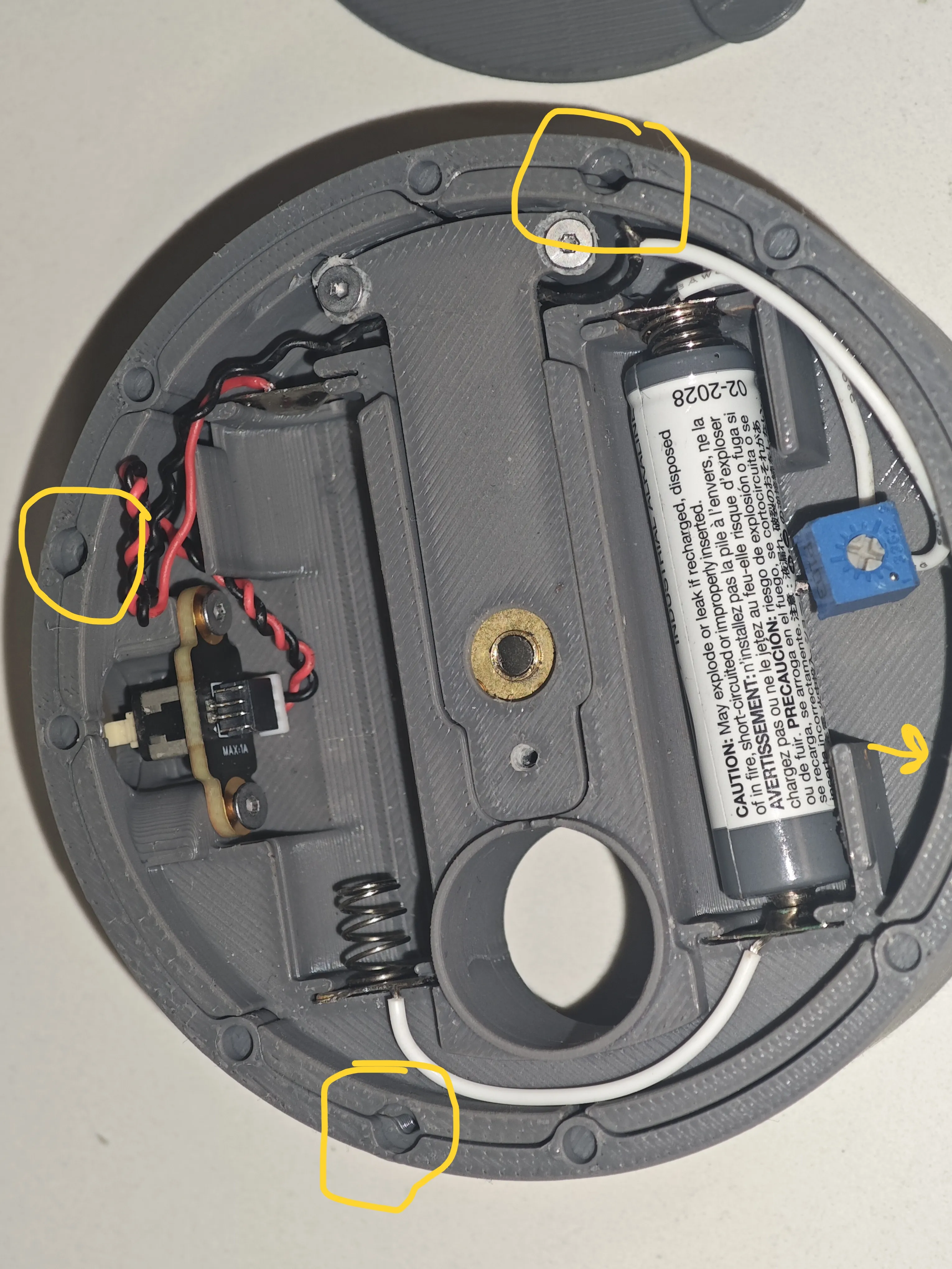
We assemble the outer cover of the motor. Those holes are for alignment if necessary. Nothing needs to be done with them if the model prints correctly. Otherwise, an M1.5 screw will be used to fix and align them
We put the cover on the motor and battery compartment. We secure it with an M2 screw
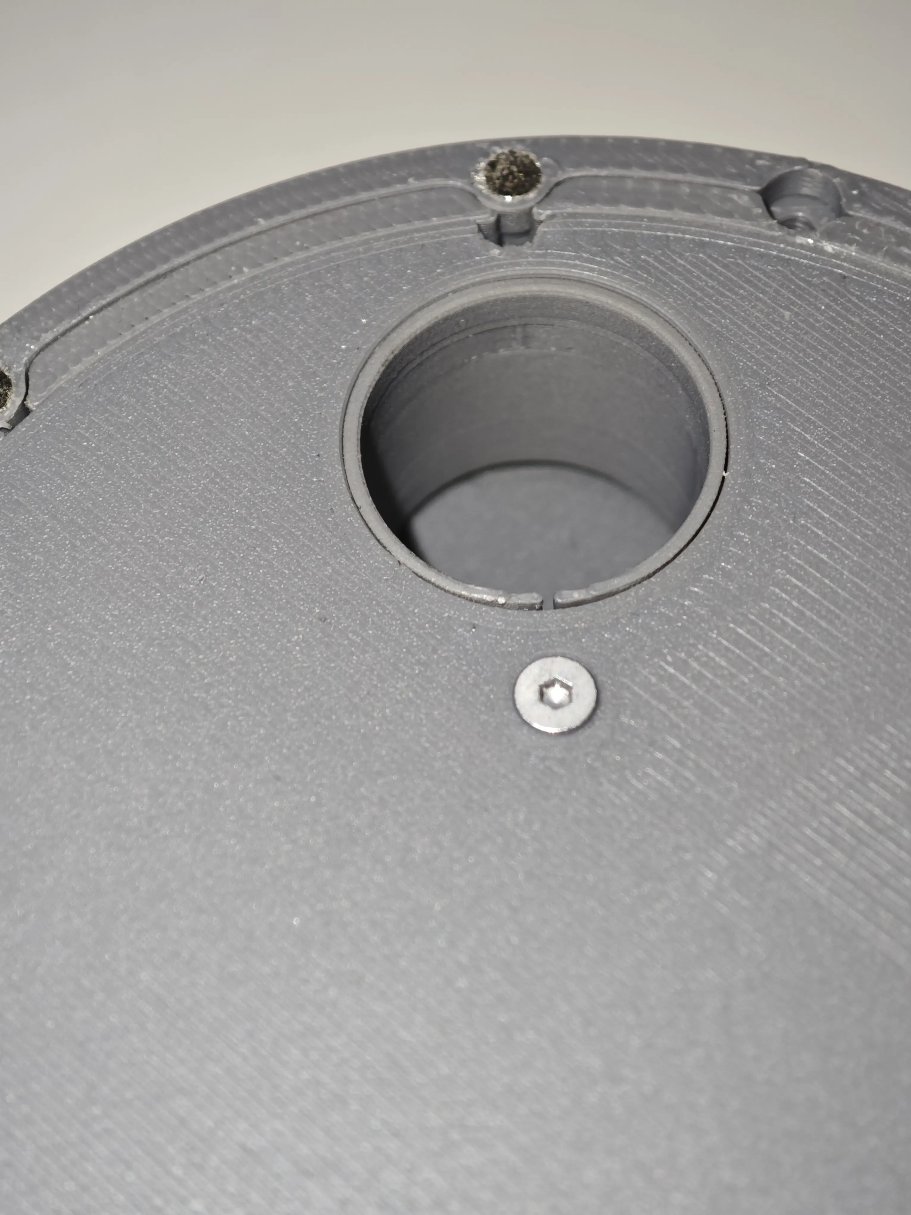
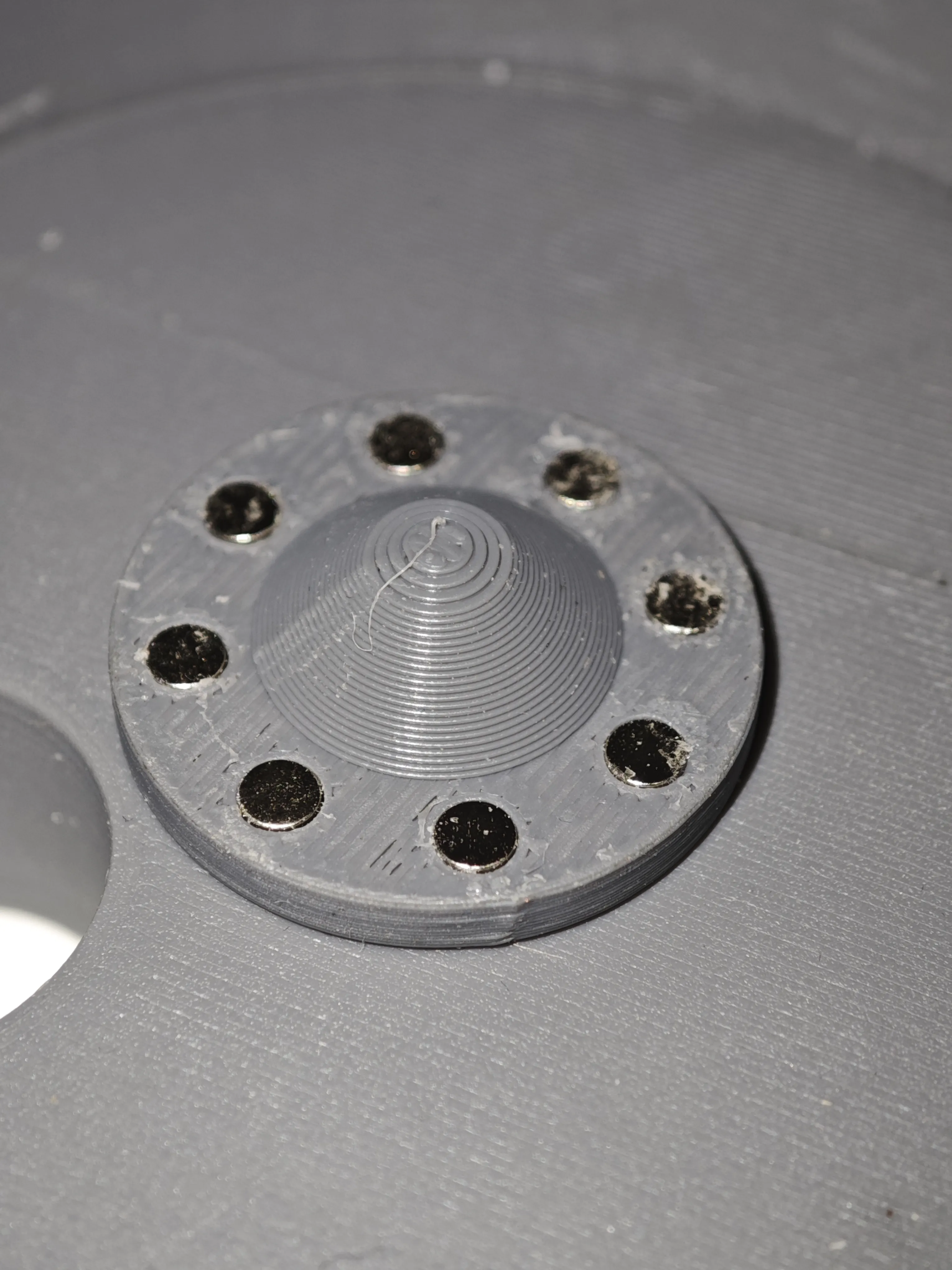
We place the magnets respecting the same polarity on the entire face. The holes for the magnets provide a correct fit on my printer, designed at 3.2mm with material expansion and glue they fit snugly, but I recommend using a 3mm drill bit, rotating it manually to clean the outside of the hole. Other ways are to use a press. Do not use heat to soften and insert the magnet
We install the magnets in the rest of the parts, respecting the polarity on each face and the inverse on the connection piece. The magnets I have used are 3x2 N52, they provide a strong hold
For the dosing elements, it is not necessary to use 8 magnets, just one is enough, moreover, with just one it will act as a clutch element if a coffee bean gets stuck. Using more magnets will stop the motor. I leave it to your preference
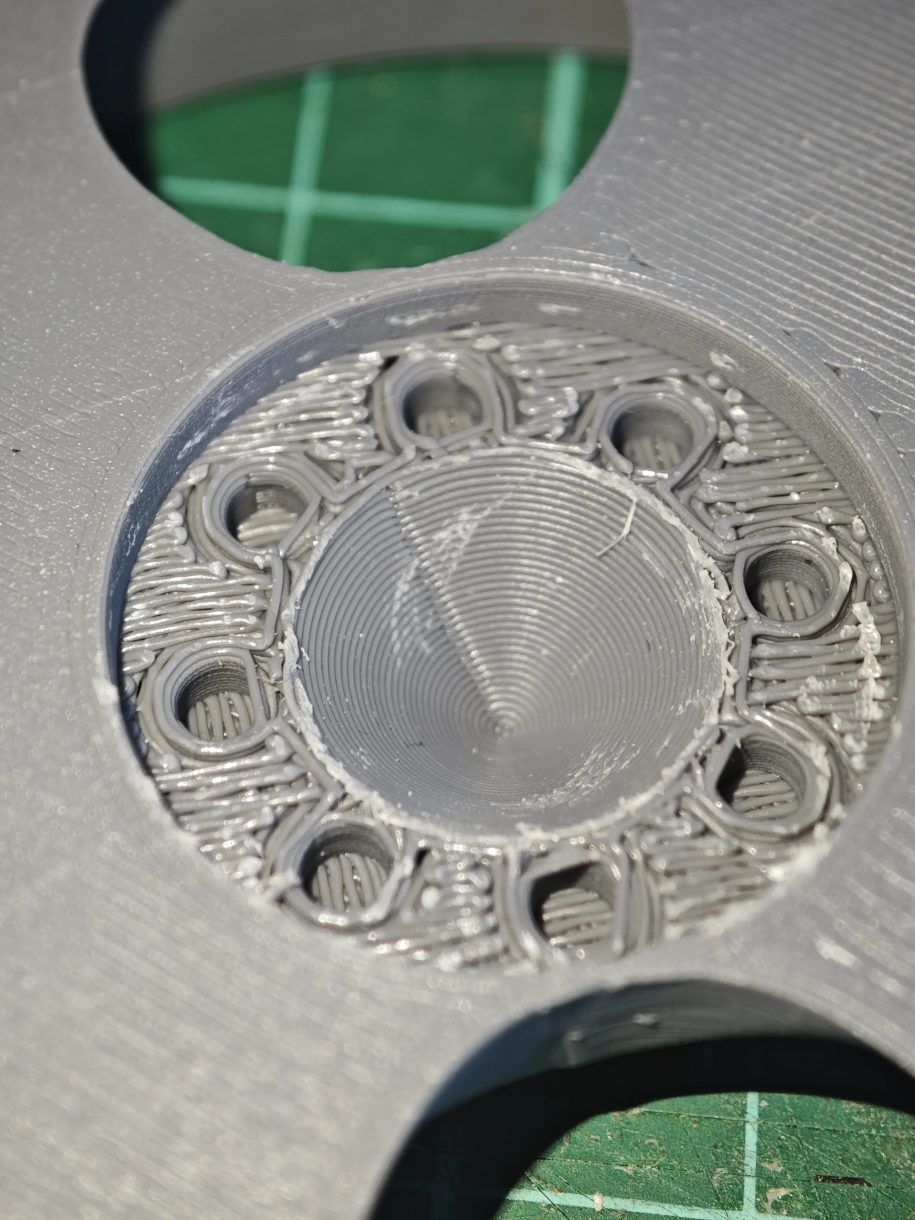
I have preferred to print the dosing parts with support and no spacing in PETG, so the finish is much nicer, but in any case, they can be used without support in PETG
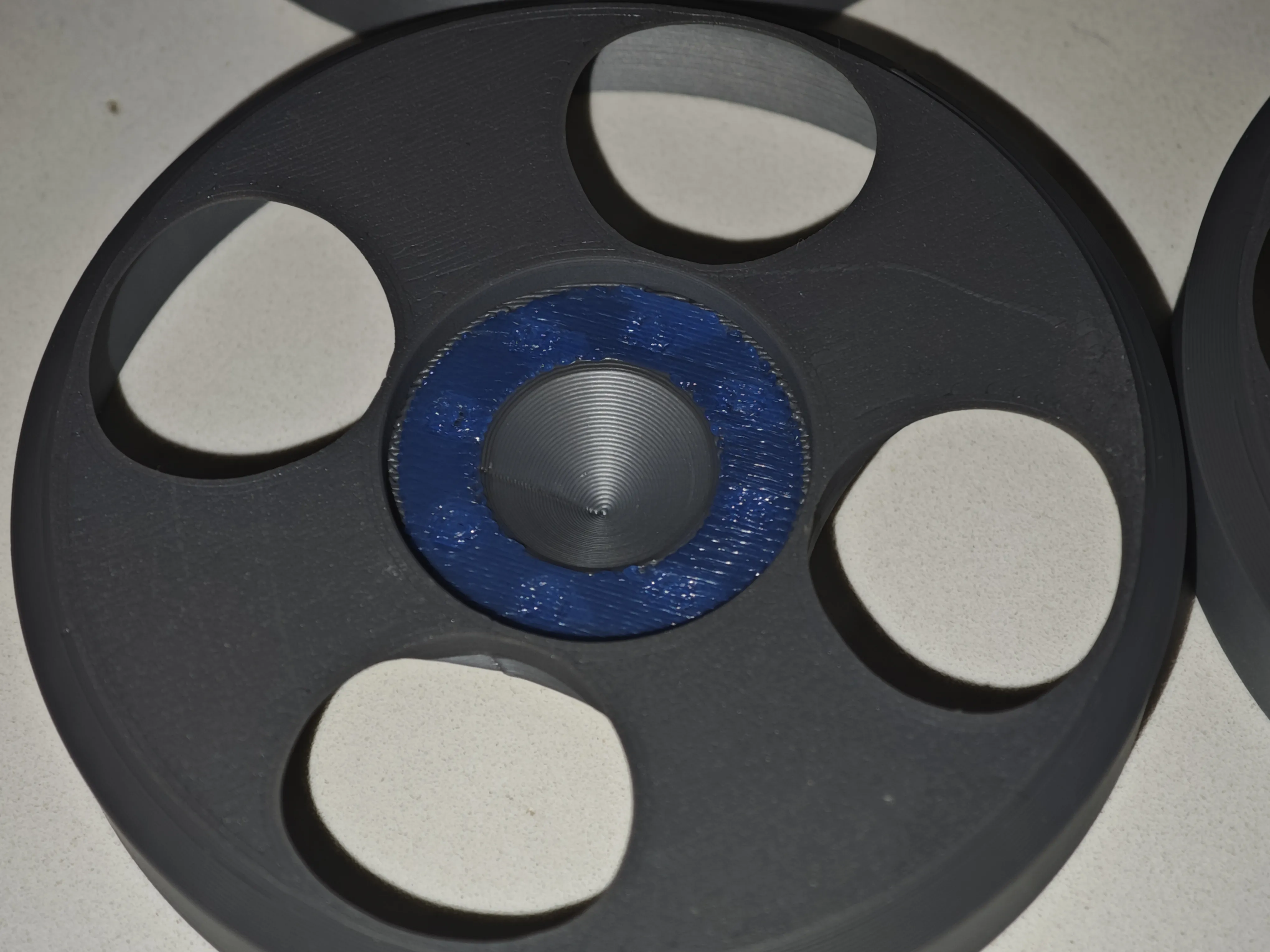
The support peels off without leaving a trace
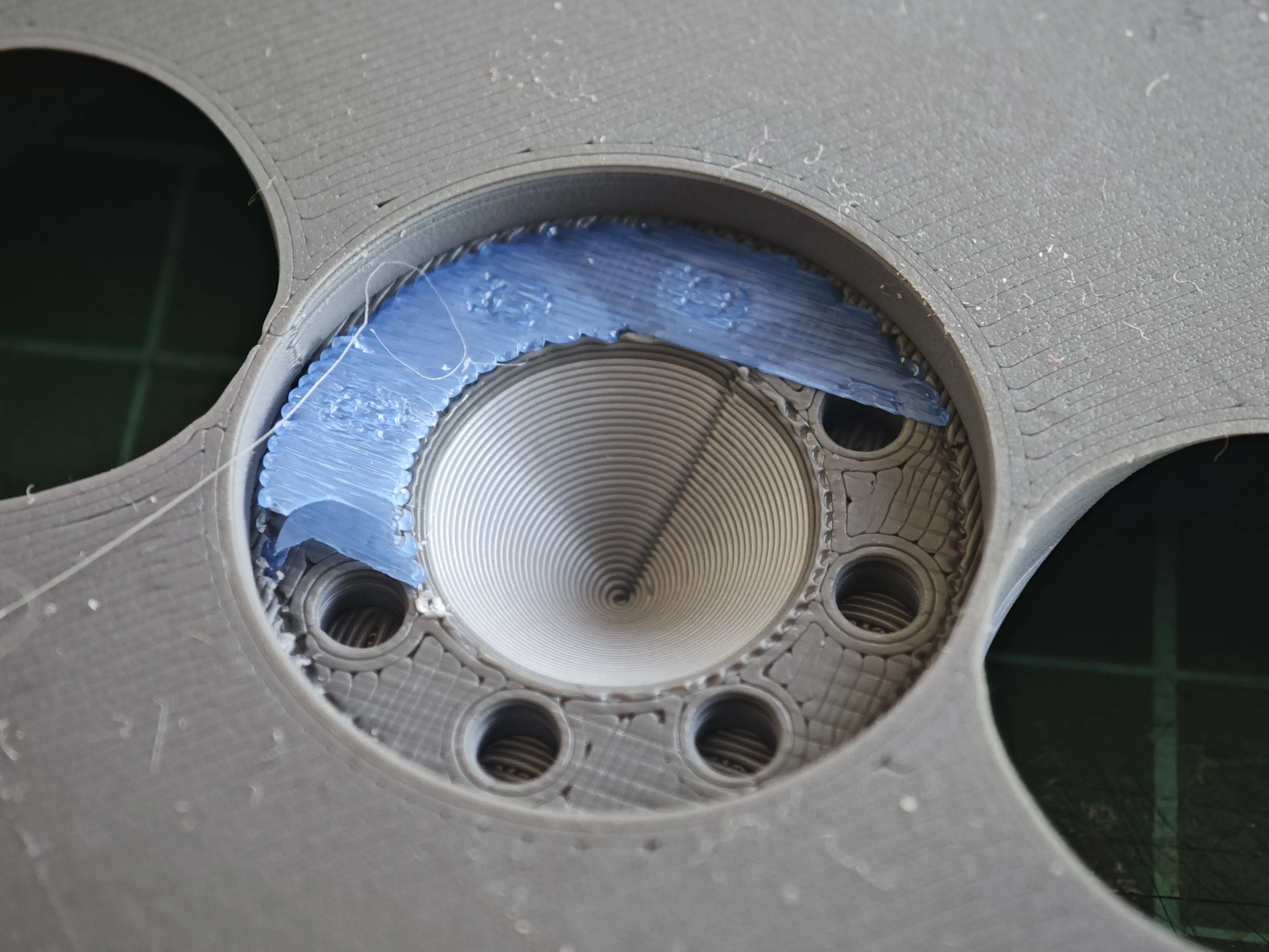
Without supports in PETG, the finish is worse, but it doesn't lose functionality
We place the dosing clutch with its magnets installed, and now we can use our coffee bean doser
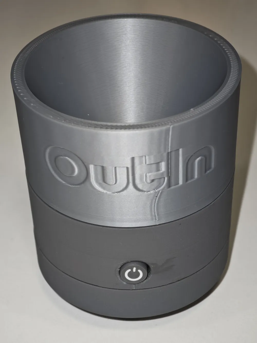
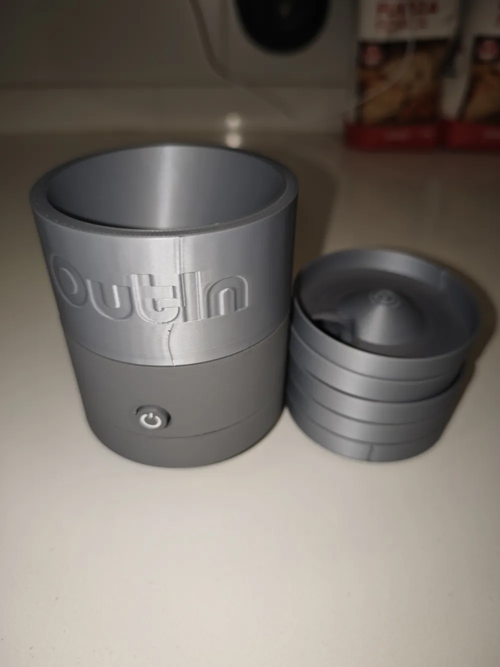
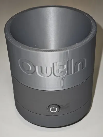
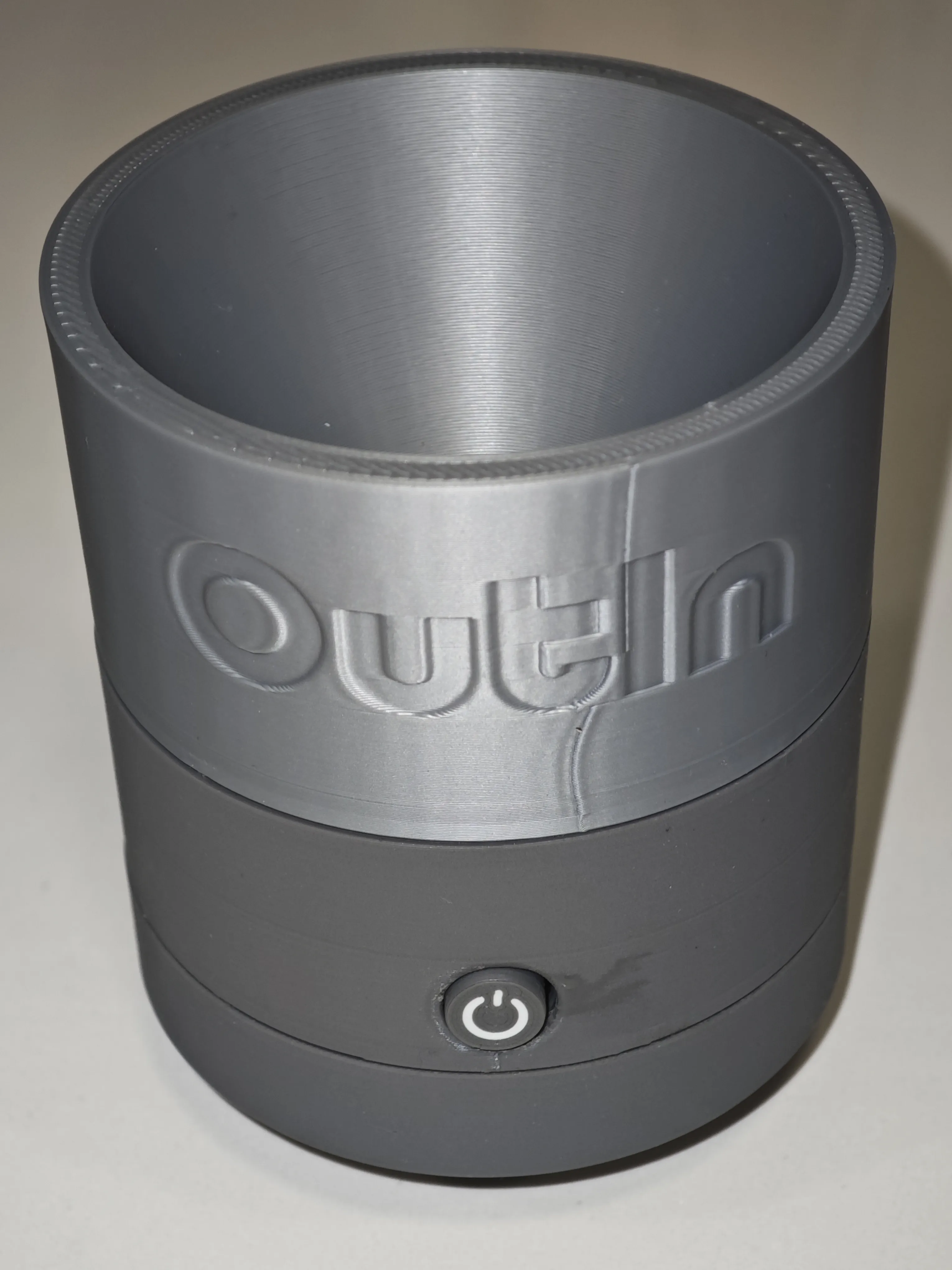
The finished product
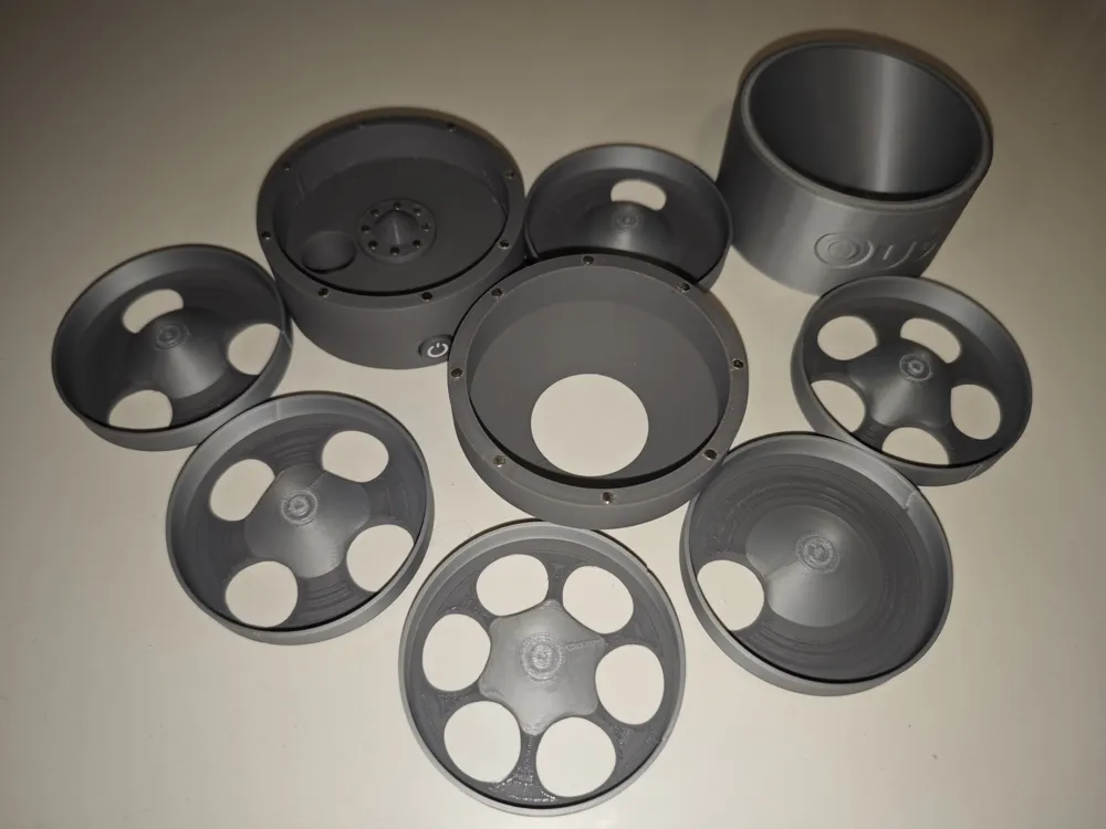
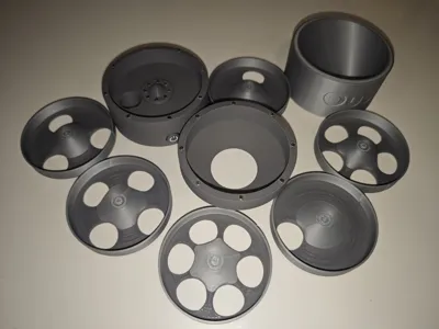
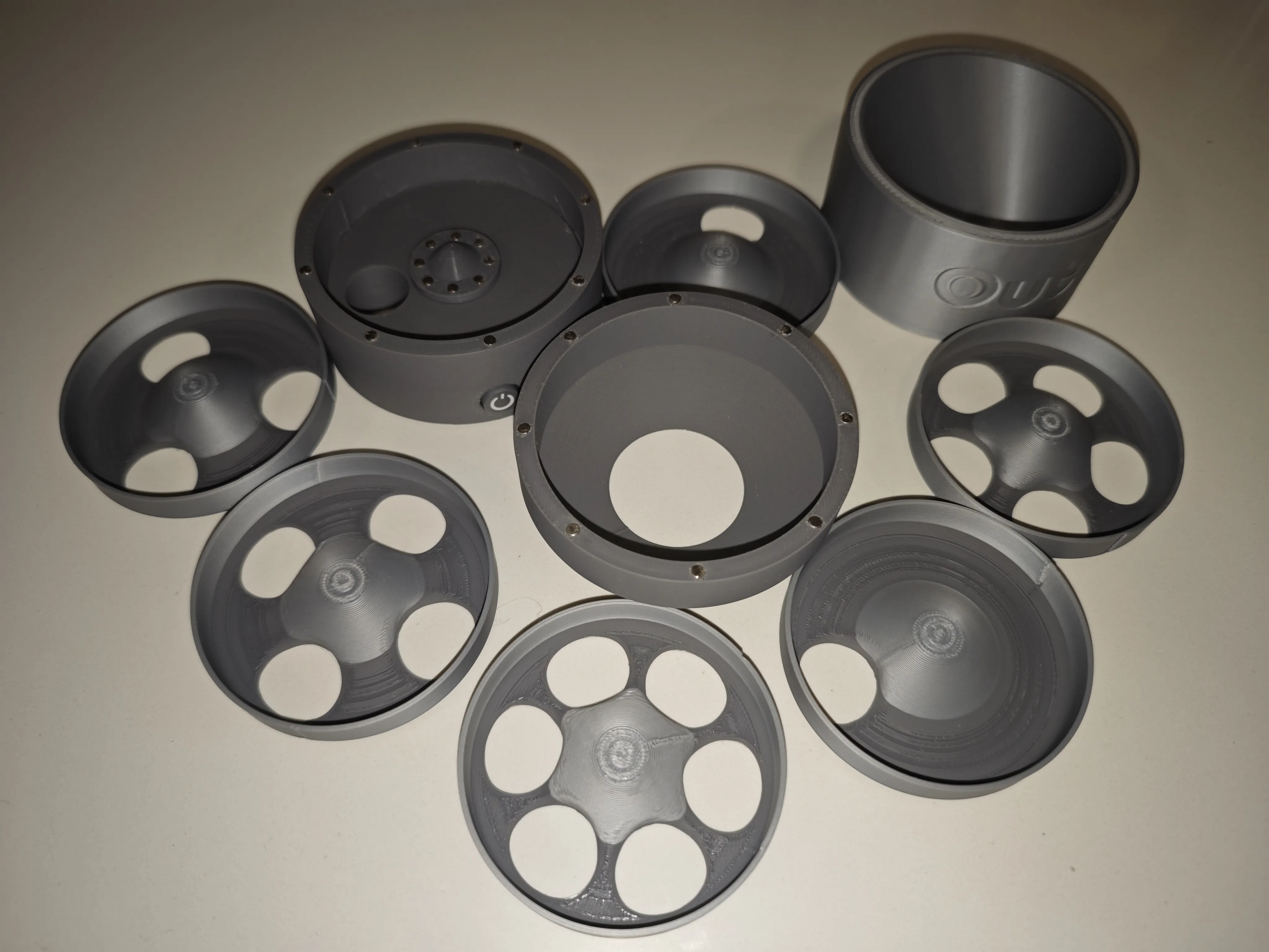
The complete kit

This is how it works

I hope you like it and enjoy it, thanks for getting this far
Boost Me (for free)
If you liked it and find it useful, you can thank me with a boost
License

You shall not share, sub-license, sell, rent, host, transfer, or distribute in any way the digital or 3D printed versions of this object, nor any other derivative work of this object in its digital or physical format (including - but not limited to - remixes of this object, and hosting on other digital platforms). The objects may not be used without permission in any way whatsoever in which you charge money, or collect fees.


Comment & Rating (12)