Pistol Grip RC Transmitter


Print Profile(2)

Description
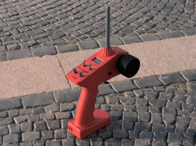
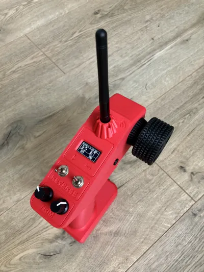
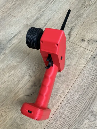
This is a pistol-style RC transmitter based on Arduino . It was created as a simple and budget-friendly alternative to commercial transmitters. It covers the basics and works well for controlling cars, boats, or other models where you don’t need a ton of channels. The design is optimized for easy 3D printing on standard printers, with no complicated parts or supports required.
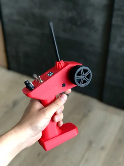
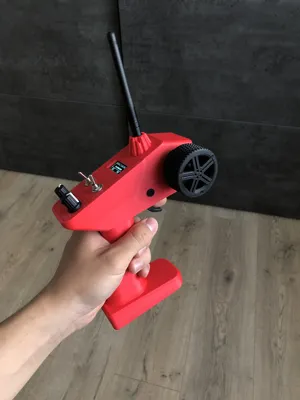
It includes a steering wheel, mounted on two bearings for smooth rotation, and a trigger used for throttle and brake control.
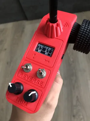
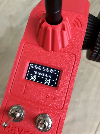
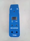
There are two rotary potentiometers used for trim adjustment, and two two-position switches that provide reversed signal control — switching the control range from 0°–180° to 180°–0°.
A 0.96-inch OLED display shows information such as battery voltage and percentage, connection status, and the positions of control elements.
This transmitter is designed to be used with my RC car models.
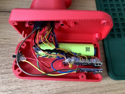
You will need:
- 1x Arduino Nano
- 1x NRF24L01 module
- 1x MT3608 Step Up Converter
- 2x 10uF 50V Capacitor
- 1x Toggle Switch
- 2x MTS-102 Toggle Switch
- 1x 0.96" OLED Display
- 15x M2.5 8mm Screw
- 17x M2.5 12mm Screw
- 14x M1.6 5mm Screw
- 1x 18650 Li-ion Battery
- 1x TP4056 Charger Module
- 2x 50kΩ Rotary Potentiometer
- 1x 1000uF 16V Capacitor
- 2x 10x15x4 Bearing
- 2x Dual-axis XY Joystick Module
- 1x 10Ω Resistor
Simple build guide:
While this is a relatively simply written build guide, assembling the transmitter is not that simple. You’ll need a bit of patience and a willingness to fine-tune things along the way.
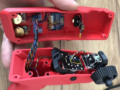
Once you download all the provided files, you’ll find a folder called "buildguide.zip" and "code.zip", which contains the source code for the transmitter. Inside the code, you’ll see the pin definitions that indicate where each component should be connected.
For example: #define pinSpeed A3
This means the joystick output for throttle control should be connected to analog pin A3. Please also take a look at the attached schematic. It is not a simple kit, but not too complicated either.
Feel free to leave a comment if anything is unclear, I’ll be happy to answer. The controller works for me, so I believe you’ll be able to get it running too.
Have fun!
UPGRADE: More Precise Control
The original KY-023 joystick suffers from noticeable inaccuracies — it has a large dead zone both in the center and at the endpoints, making it difficult to control RC models with precision.
To improve performance, I replaced the KY-023 with a joystick from a PS5 controller, which uses a high-quality Hall Effect sensor. The result is significantly smoother and more precise control. I ordered this joystick:
There are two options how to do it:
Option 1: Replace Only the Hall Effect Sensor
The PS5 joystick has a different footprint than the KY-023, but it is possible to remove only the Hall sensor from the PS5 joystick and solder it onto the KY-023 module.
Note: You must reverse the power connections — connect VCC to GND and GND to VCC — due to the sensor’s internal design.
This method works, but requires some soldering and care.
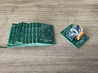
Option 2: Custom PCB for PS5 Joystick
I designed a custom PCB that matches the PS5 joystick’s footprint but keeps the same outer dimensions as the KY-023 module. This allows for a direct drop-in replacement without needing to modify the 3D-printed model.
This solution is highly recommended for its precision, reliability, and ease of installation.
Calibration and EEPROM
The firmware has been updated to support joystick calibration, with all settings stored in EEPROM. Calibration is only needed once, unless no valid configuration is found in memory.
Manual calibration can also be triggered by setting both trimmers to their minimum positions before powering on the controller. Follow the on-screen instructions to complete the process.
Documentation (1)
License
You shall not share, sub-license, sell, rent, host, transfer, or distribute in any way the digital or 3D printed versions of this object, nor any other derivative work of this object in its digital or physical format (including - but not limited to - remixes of this object, and hosting on other digital platforms). The objects may not be used without permission in any way whatsoever in which you charge money, or collect fees.
Comment & Rating (33)