Search models, users, collections, and posts

Harry Potter Wand Hermione Remote Control 433MHz
Remixed by
IP Report
GIF

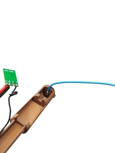
Print Profile(4)

wand_hermione_pt1 - 0.2mm nozzle, 0.08mm layer, 4 walls
Designer
5.4 h
1 plate

wand_plug-in-module - 0.2mm nozzle, 0.08mm layer, 4 walls
Designer
2.1 h
1 plate

wand_hermione_pt2 - 0.2mm nozzle, 0.08mm layer, 4 walls
Designer
2.4 h
1 plate

wand_connector - 0.2mm nozzle, 0.08mm layer, 4 walls
Designer
26 min
1 plate
Open in Bambu Studio
Boost
62
142
6
6
135
20
Released
Description
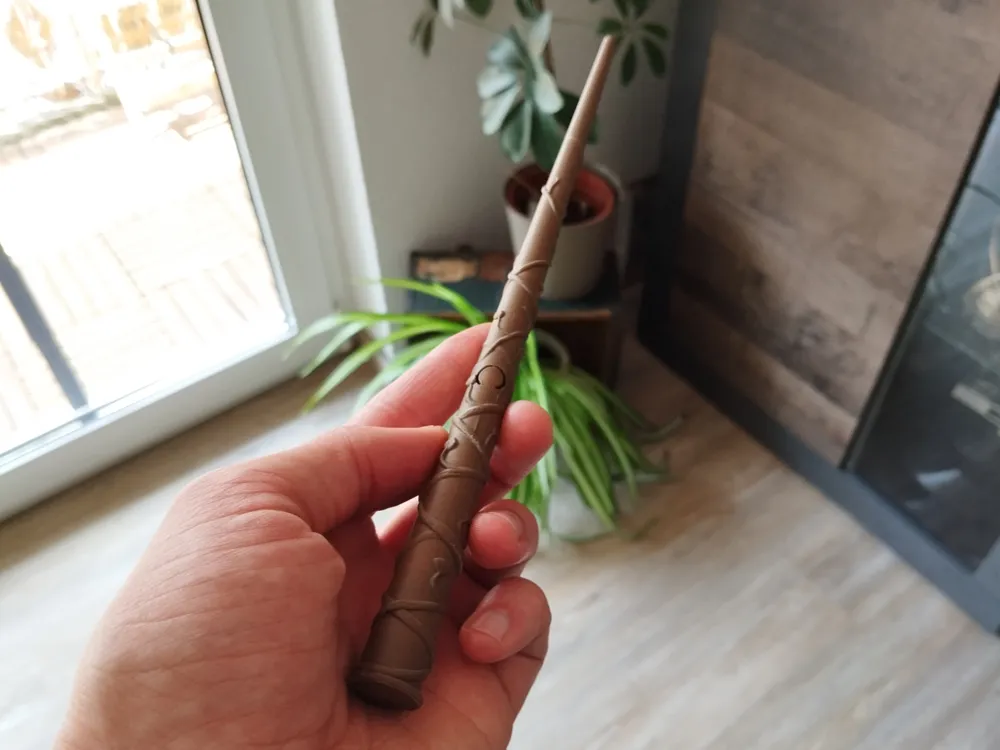

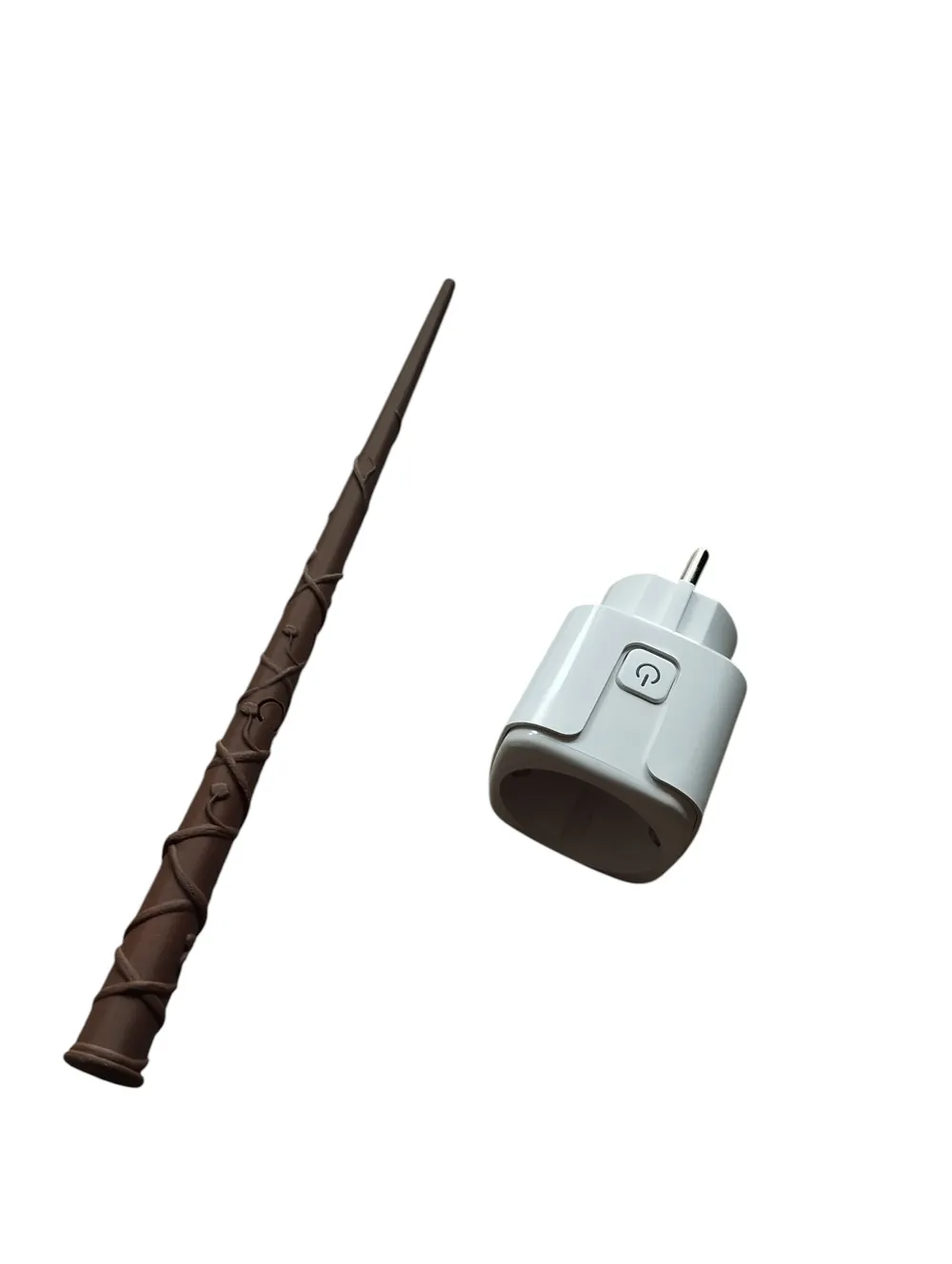
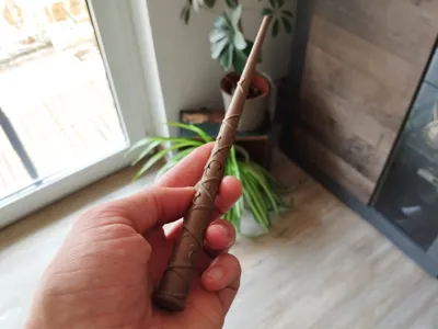
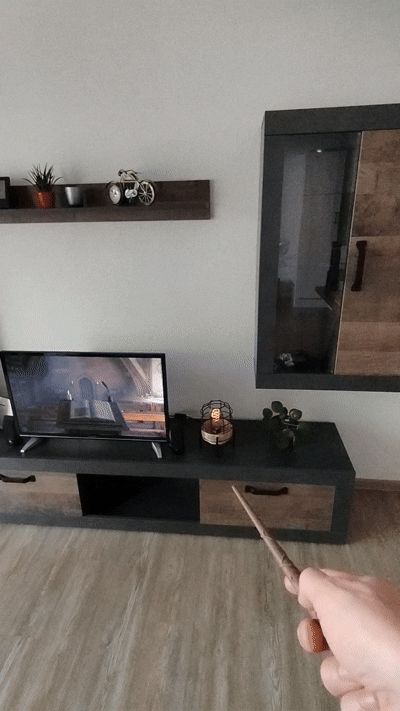
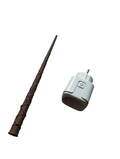
This is a magical wand designed to control a lamp with a simple flick, just like in the wizarding world! The wand functions as a remote control for 433 MHz smart plugs, allowing you to switch the lamp on and off with a wave of the wand. It works on the common 433 MHz protocol, making it compatible with many wireless smart plugs. Ideal for Harry Potter fans who want to add a touch of magic to their everyday lives!
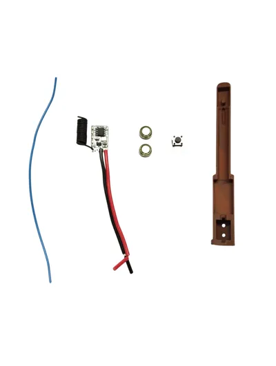
Required Parts
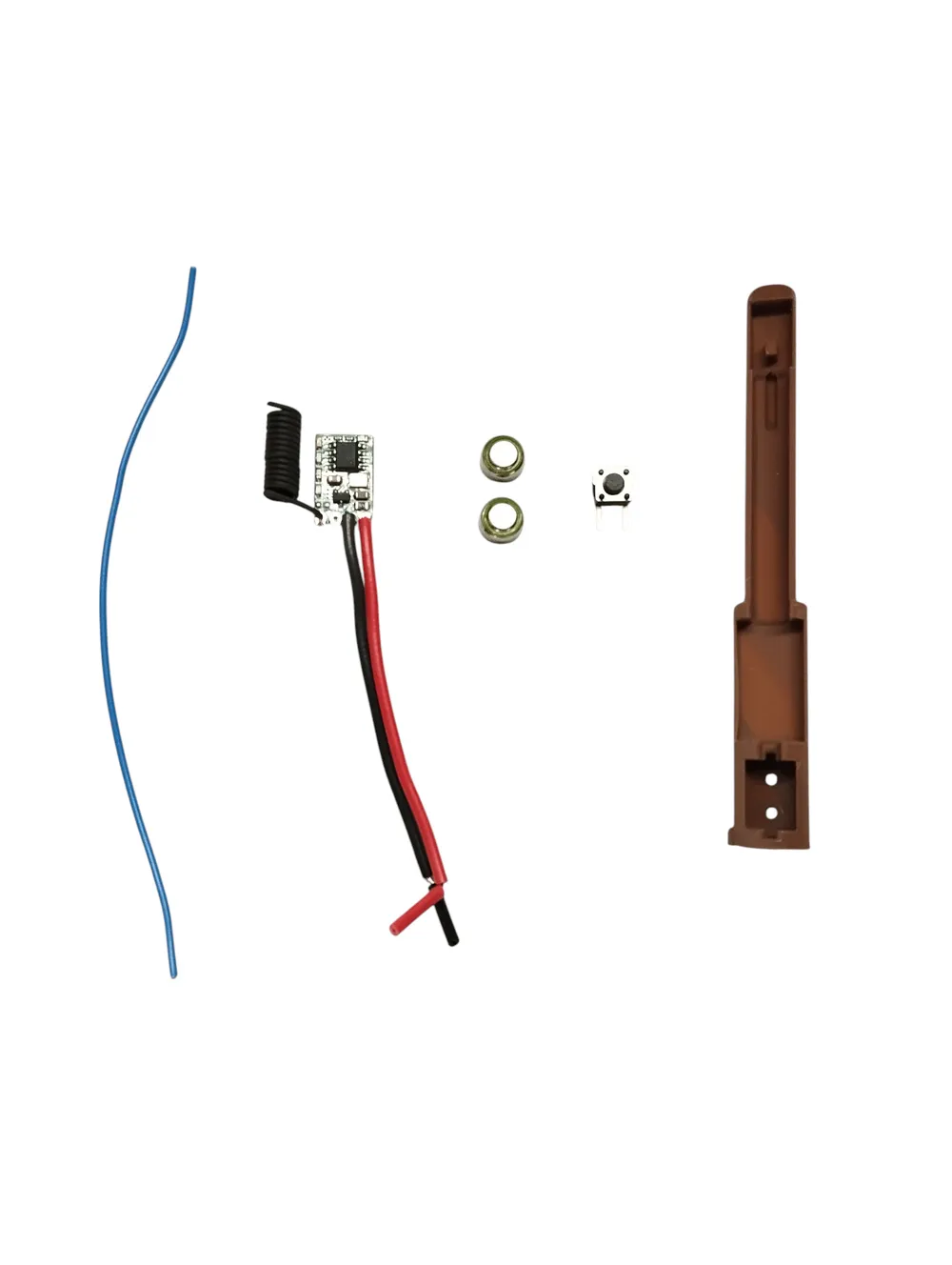
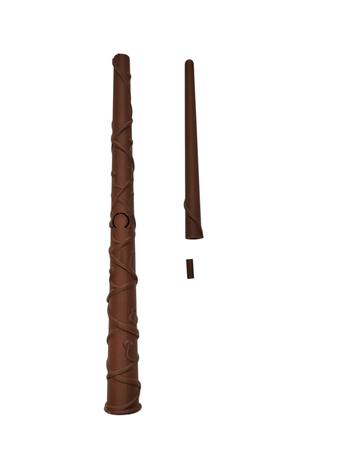
3D Printed Components:
- wand_hermione_part1.3mf
- wand_hermione_part2.3mf
- wand_connector.3mf
- wand_plug-in-module.3mf
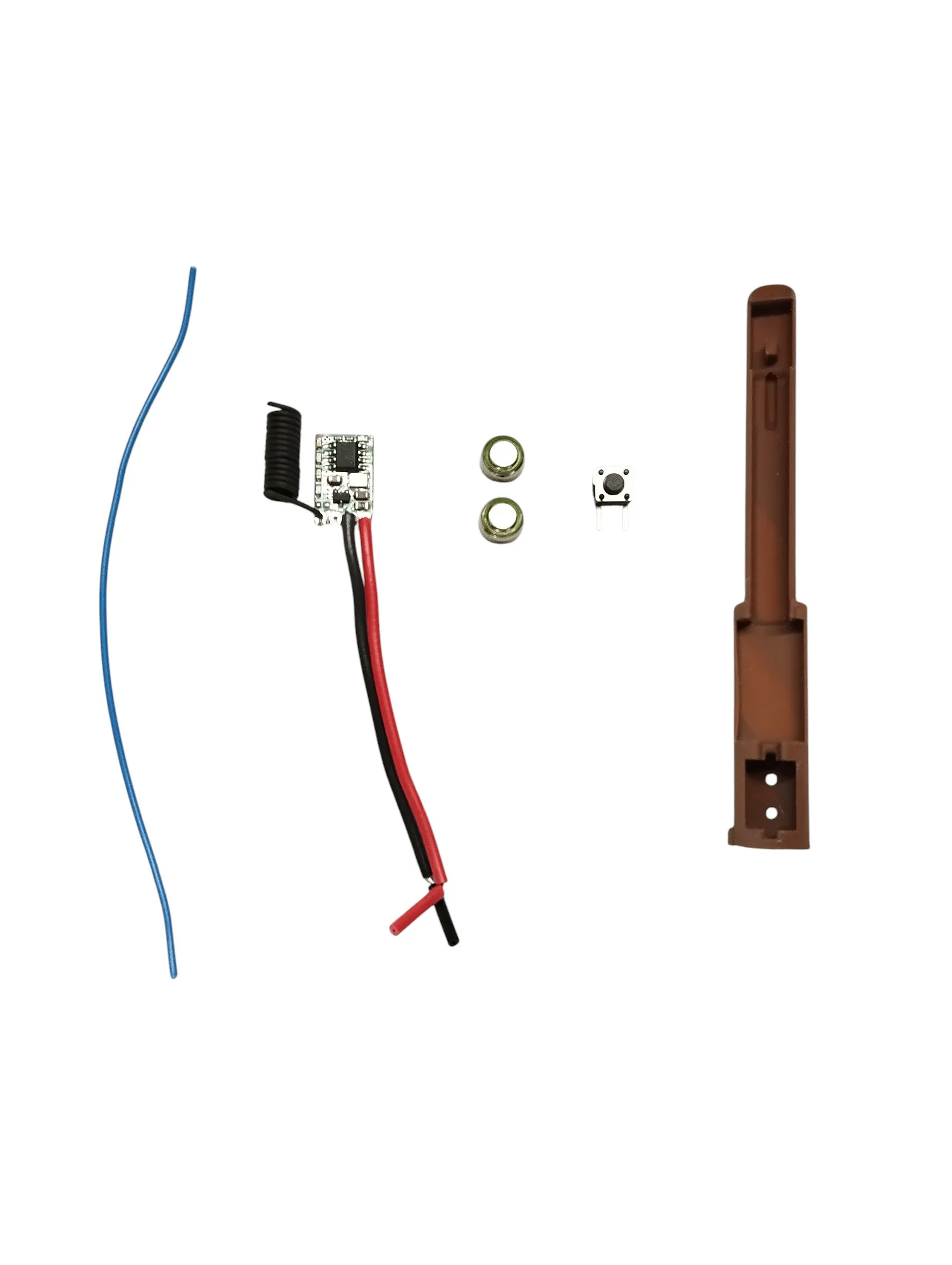
Electronics:
- 1× 433 MHz wireless smart plug (Aliexpress) https://www.aliexpress.com/item/1005008284515388.html
- 1× 433 MHz RF Wireless Transmitter Module (Aliexpress) https://www.aliexpress.com/item/1005007574184495.html
- 1× Microswitch (Aliexpress) https://www.aliexpress.com/item/1005006357859519.html
- 2× Button cells AG5 / LR754
- approx. 12 cm of wire (0.25 mm²), preferably flexiblel
Step 1 – 3D Printing
Download the .3mf files and print all components.
Recommended print settings:
- Material: PLA
- Nozzle diameter: 0.2 mm
- Layer height: 0.08 mm
- Supports: Only if necessary (e.g. for the handle or internal structure)
Post-processing:
- Carefully remove all support structures using flush cutters or a hobby knife.
- Make sure the mating surfaces on the tip and handle are clean and smooth.
- Glue the tip of the wand to the handle using a small drop of superglue. Hold the parts in position for a few seconds until the glue sets.
- Optional: Lightly sand any rough areas with fine-grit sandpaper for a smoother finish.
Step 2 – Preparing the Electronics
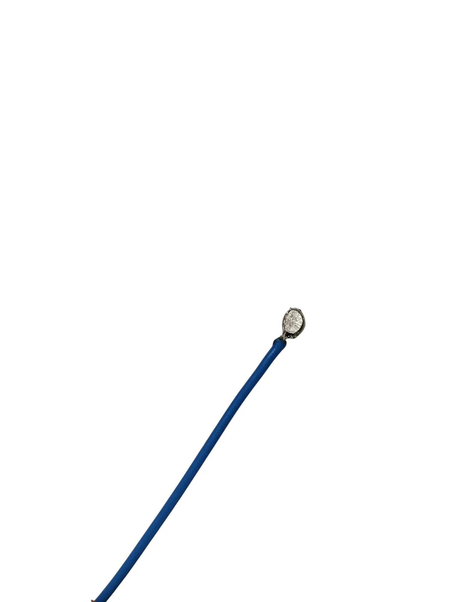
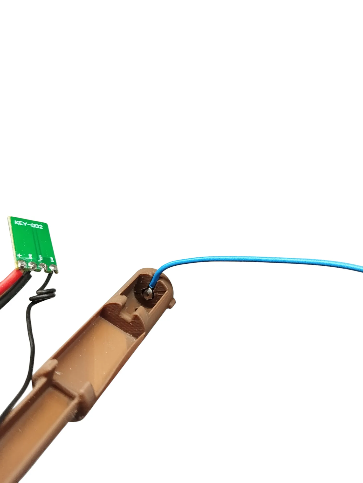
Prepare the wires
- Strip approximately 2–3 mm of insulation from both ends of the red and blue wires.
- Red = positive terminal, Blue = negative terminal for power supply.
- Tin the stripped ends with solder until a small droplet forms.
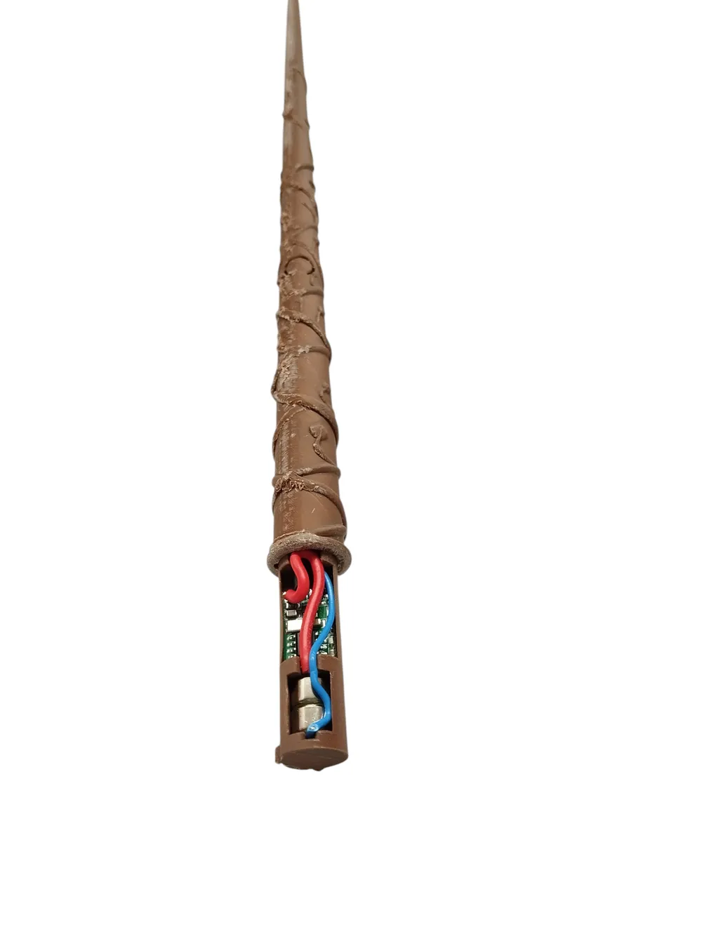
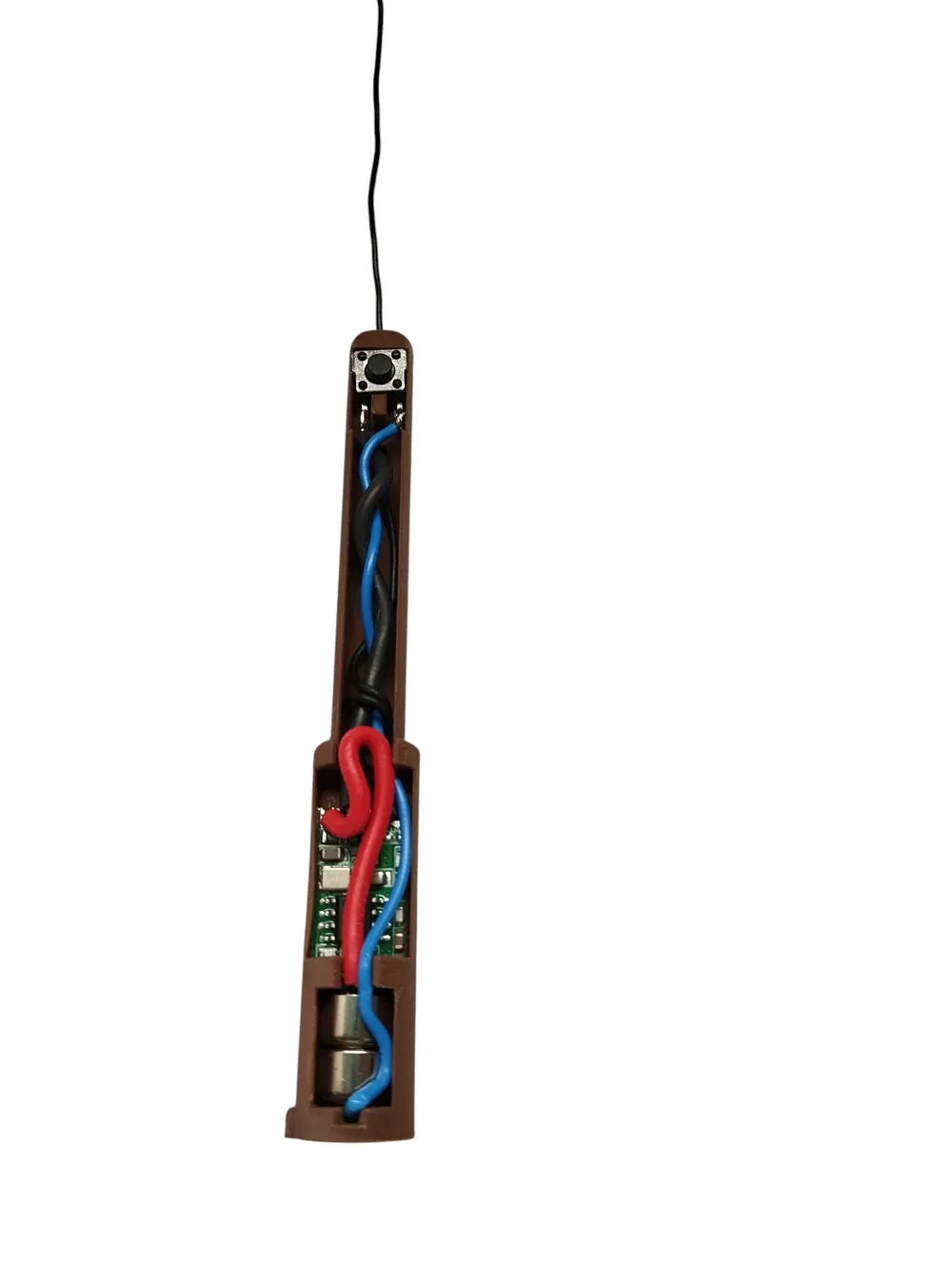
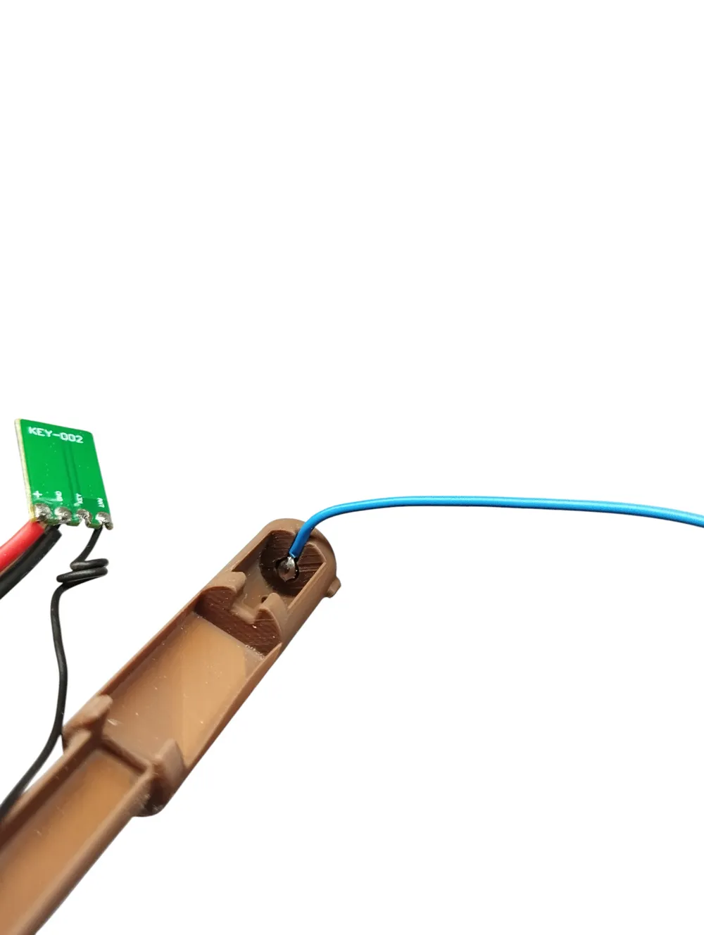
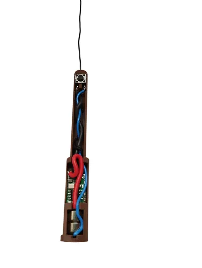
- Carefully flatten the solder droplet using flat-nose or needle-nose pliers so it fits precisely into the recess of the battery holder (see photo).
Insert the batteries
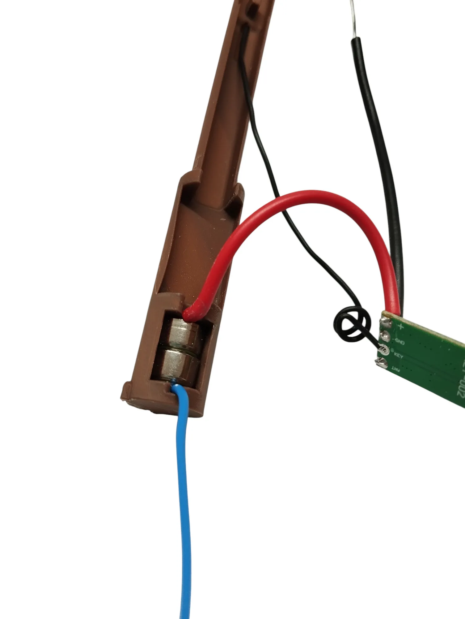
- Insert two button cells (AG5 / LR754) into the designated battery holder.
- Make sure to observe correct polarity: positive (red) on top, negative (blue) on the bottom.
Route the antenna
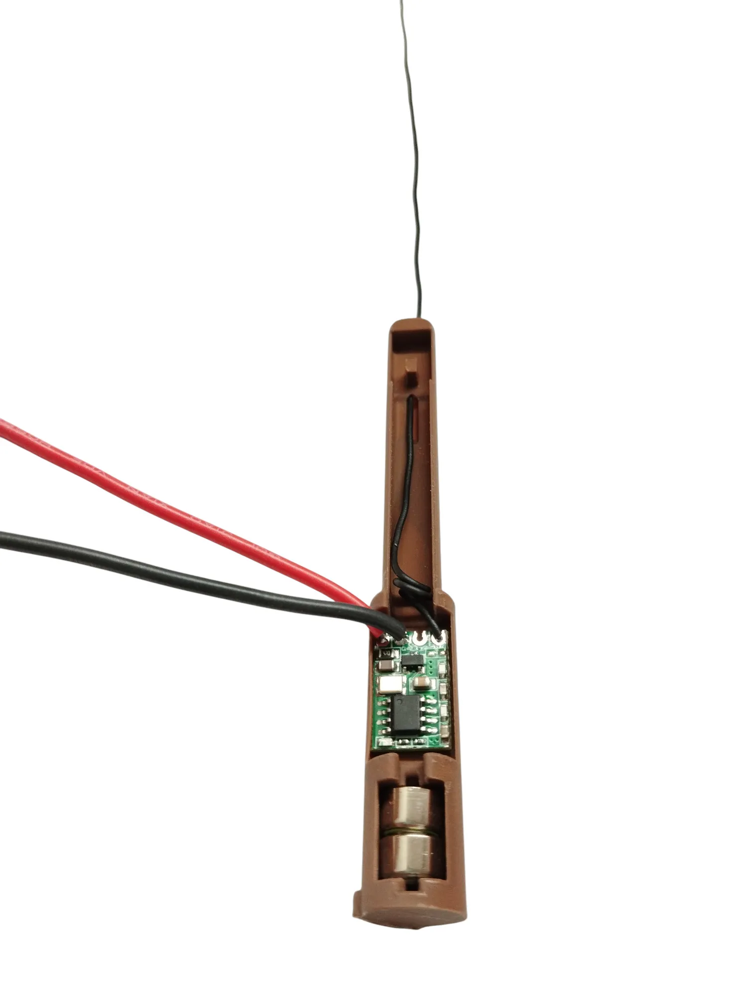
- Guide the antenna wire of the 433 MHz module through the designated opening behind the microswitch.
- Make sure the wire is not pinched or bent, as this can affect transmission range.
Prepare the microswitch
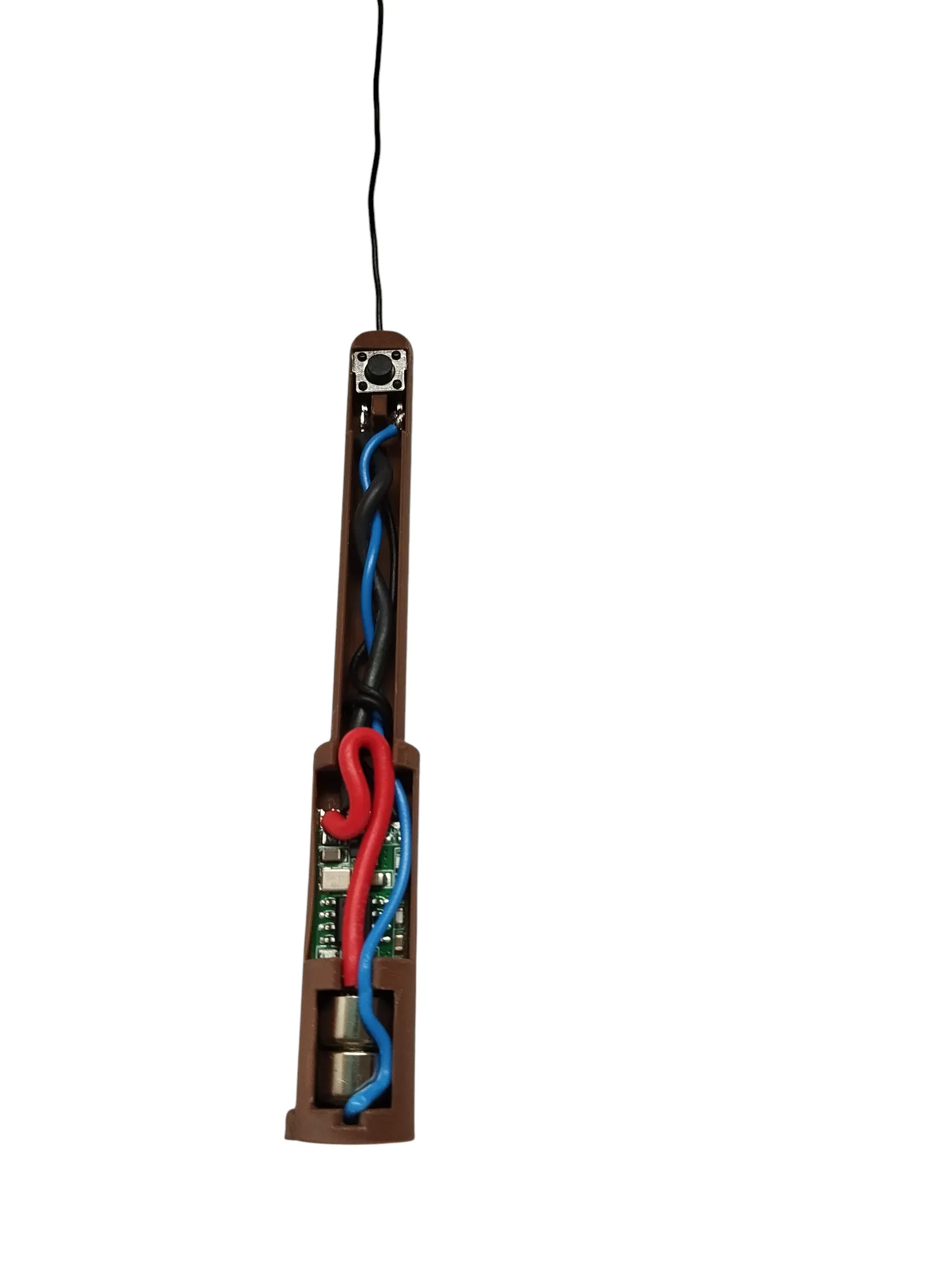
- Carefully remove the side metal mounting tabs from the microswitch using needle-nose pliers until only the two metal contacts remain visible.
- Lightly tin both contacts to make soldering easier later.
Connect the signal wire
- Solder the black wire from the 433 MHz transmitter module to one of the two contacts on the microswitch.
- Connect the ground wire
- Solder the blue wire (negative battery lead) to the second contact on the microswitch.
- This wiring allows the transmitter module to be activated via the microswitch.
Step 3 – Assembly
- The completed 433 MHz electronics module is now carefully inserted into the wand's housing.
- Pay attention to the correct orientation: Two guide pins inside the housing ensure the module is positioned correctly.
- The module should snap into place or fit securely without the need for force.
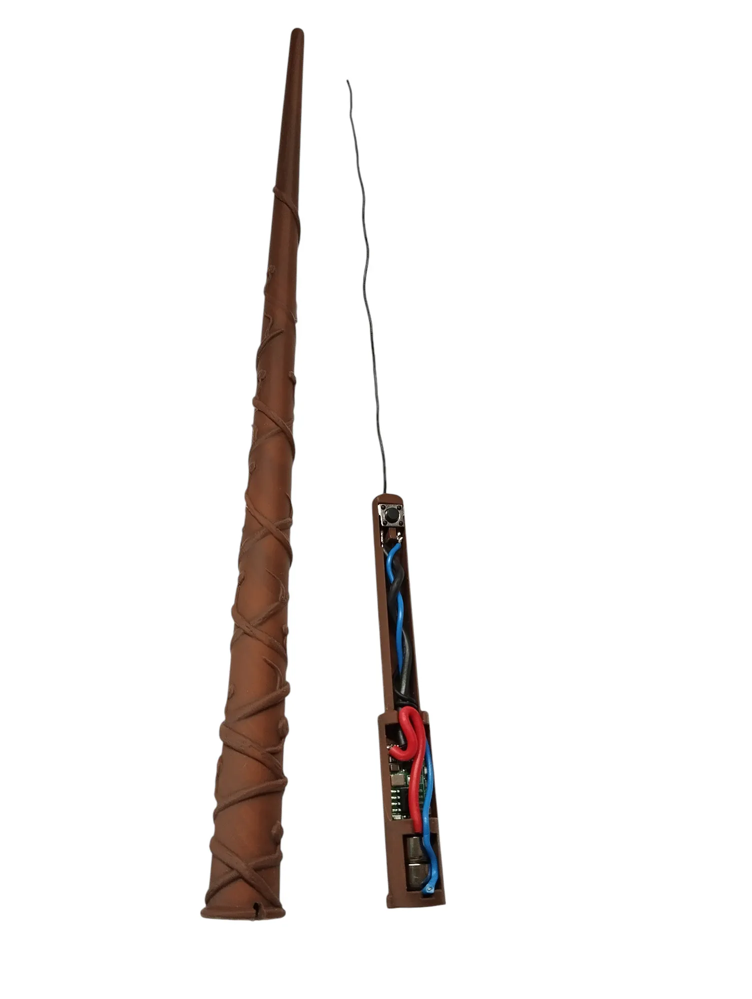
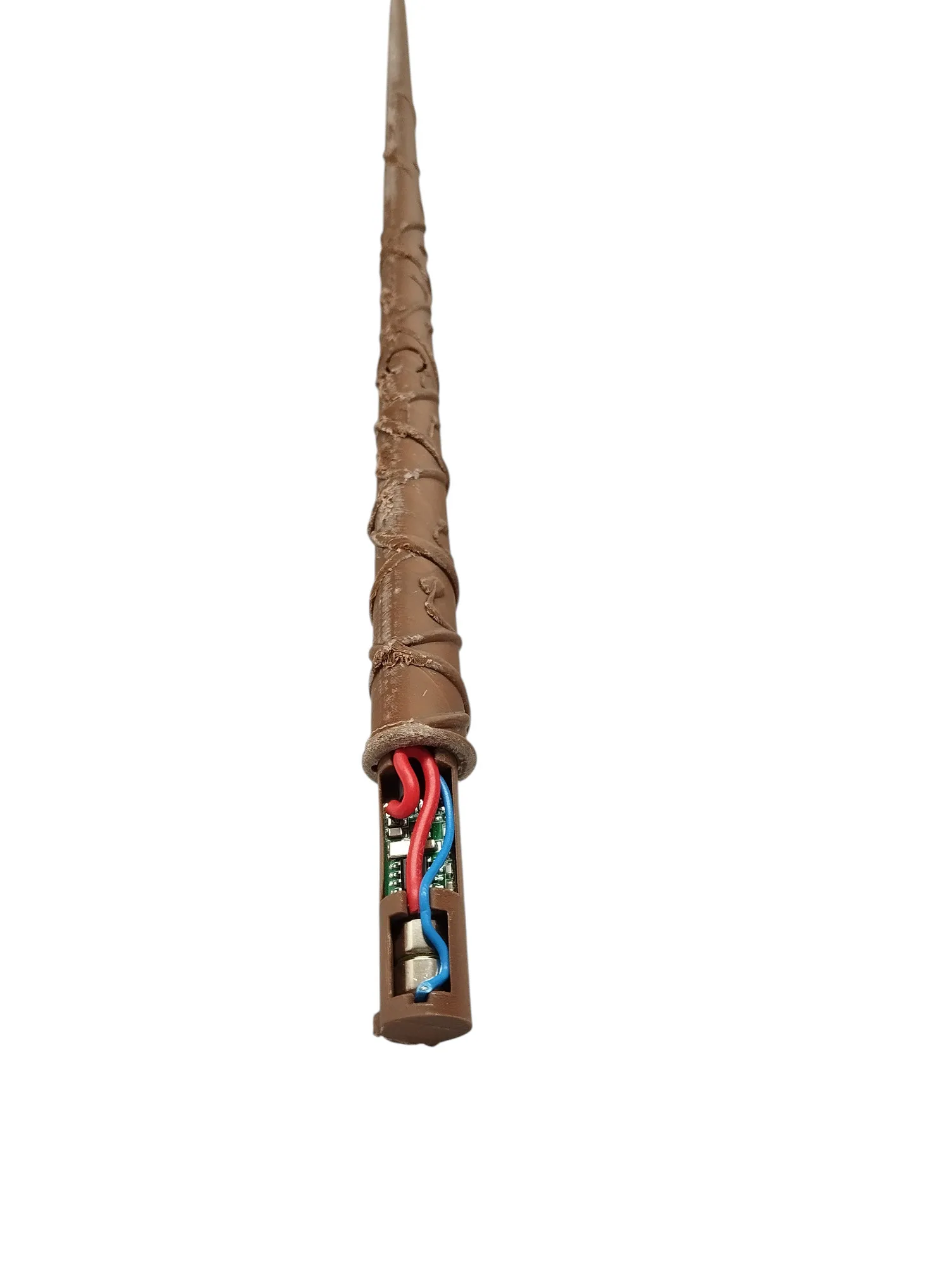
Maintenance Notes:
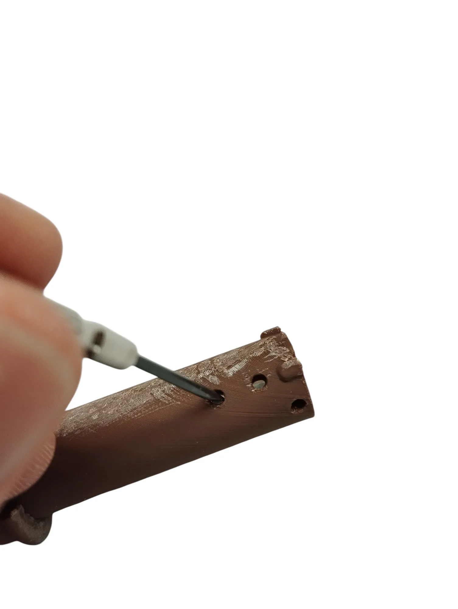
- There is a small hole on the underside of the wand.
Through this hole, you can carefully push out the button cells using a needle or a small screwdriver to replace them if necessary.
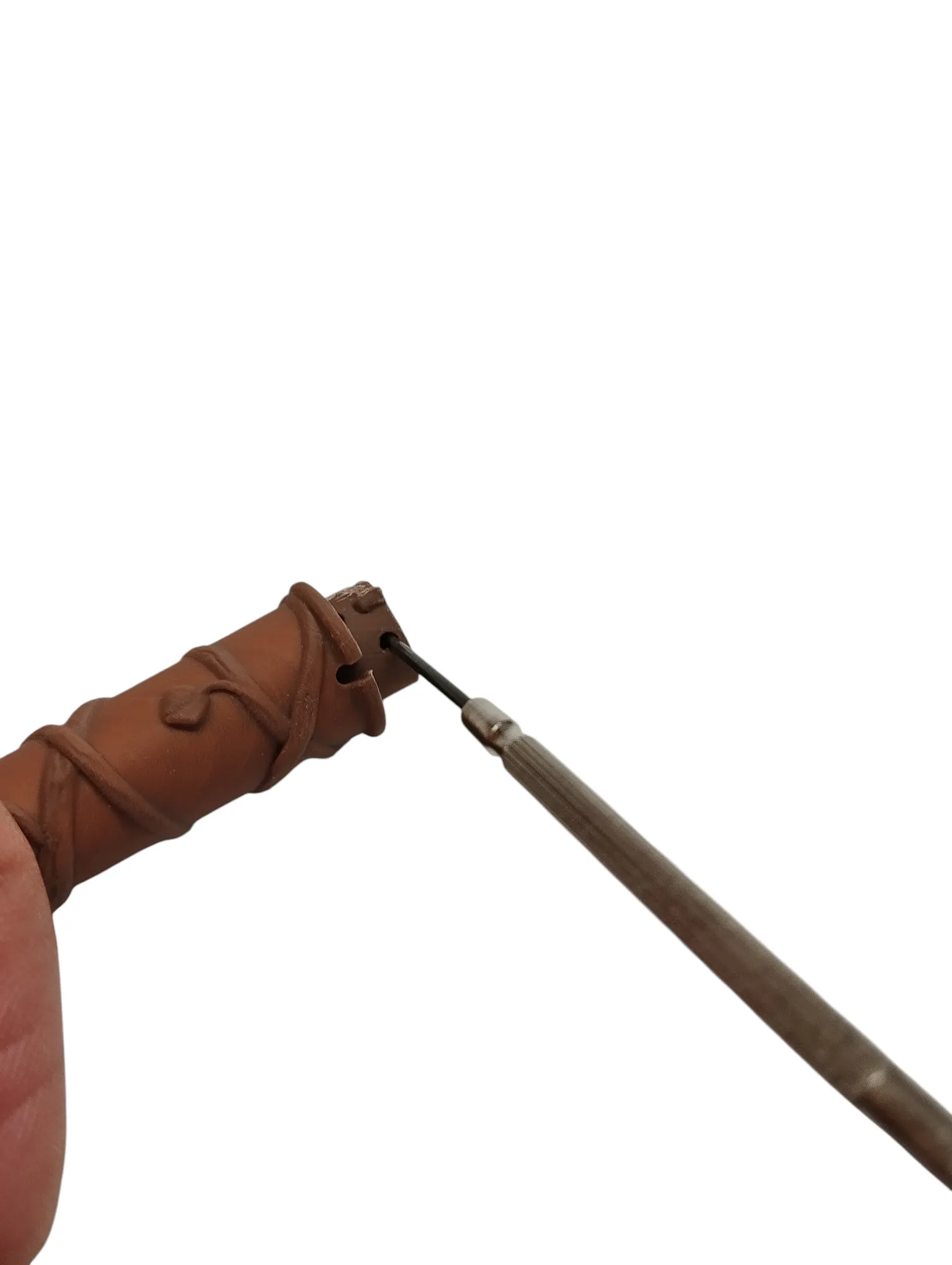
- To open the wand, the entire electronics module can be removed:
Use a small screwdriver to gently pry the module out from the lower tab.
Be careful to avoid damaging the housing during this process.
Step 4 – Pairing with the Smart Socket
Plug in the smart socket
- Ensure that it is powered on.
Put the socket into pairing mode
- Press and hold the connection button on the smart socket for about 3 seconds until the LED starts blinking (depending on the model).
Pair the wand
- Press the microswitch on the wand three times in quick succession.
- This will send the pairing signal from the 433 MHz transmitter.
Function test
- Press the switch again. The socket should now toggle (on/off).
- Depending on the socket model, the "Toggle" mode is supported (state changes with each signal).
This remix is based on


License

This user content is licensed under a
Creative Commons Attribution-Noncommercial-Share Alike


Comment & Rating (6)