3-Blade Wind Turbine v2


Print Profile(2)


Bill of Materials


Description
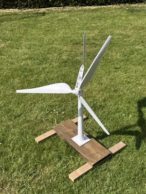
Introducing the new v2 of the 3-blade wind turbine I designed. It's redesigned for printing on both the X1 series and the new H2D, as it's quite large and leverages the latter's increased print volume.
For assembly, you'll need 5 M3 screws, 3 M3 nuts, 4 608ZZ ball bearings (8mm X 22mm X 7mm), and optionally 2 long M4 screws (between 35 and 60 mm).
The v2 improvements are:
- Complete redesign to make the turbine printable on X1, P1, and X1C series.
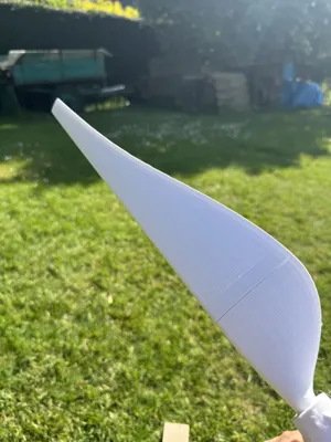
- I modeled a new blade: more aesthetically pleasing, aerodynamic, and larger. It comes in two versions: one printable on X1 machines and an H2D version where the connection between the two half-blades is located at the widest point of the blade to optimize the bonding surface.
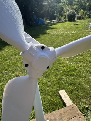
- A new, larger axle to accommodate the blades, which now have increased diameter mounts for added strength. The blade axles also have a hole for reinforcement with M4 screws, though I haven't done this yet, as I've never had issues with blade strength.
- Extended fuselage and enlarged tail assembly to improve wind orientation sensitivity.
- Modification of two potential weak points on the rotation axes that work in the direction of layer separation, thus in the weakest direction. I've added 3.8mm holes for screwing in a long M4 screw to permanently reinforce these weak points.


- New, wider pivot for increased strength while maintaining the flexibility to adjust the center of gravity and balance the turbine on its vertical axis.

As with v1, the blade pitch is adjustable to adapt the turbine to the wind strength at your location. The stronger the wind, the less the blades will open…
The primary purpose is currently decorative. Given its excellent performance and the high torque generated on the axis, I added a square end to the axis to allow for extensions (dynamo, etc.), but these are not yet implemented. The passage of current from the orientable head and the base is already provided thanks to the presence of two bearings on the vertical rotation axis of the wind turbine. Currently unused.
This is a completely original creation. If you wish to access the model, it is available on my OnShape account: https://cad.onshape.com/documents/5cff8755ad4de36b6ef00cc1/w/795611aff176dbe40851db77/e/3008a80d0b1de86351a71d0d
Feel free to modify/adapt the model; I would simply appreciate you letting me know so I can be inspired by it in the future…
Boost Me (for free)
If you appreciate this work, feel free to help me out with a small boost :)
Comment & Rating (42)