


Print Profile(1)

Bill of Materials
- usb适配器 x 1:
Description
Placeholder
Boost Me (for free)
FREE BOOSTS for FREE MODELS! 🚀
Assembly Instructions:
Arms: Assemble the shoulders as illustrated, in this sequence: attach [tire chassis 2] to [body 4], then [ratchet 1 and spring plate] to [tire 2], and finally [hub 3] to [ratchet 1]
A snug fit between the central ratchet and body pins is normal, preventing limb detachment. I recommend printing this section with my settings; I've increased the infill to 100%
Assembly Guide:
Arms: shoulders as shown, the order is: [tire chassis 2] to the body 4] [ratchet 1 and spring plate] to the tire 2], [hub 3] to ratchet 1]
It is normal for the center ratchet and body pins to fit tightly to prevent the limbs from falling off. It is recommended to use my print settings. The infill for this section has been modified to 100%


————————————————————————————————————————————————————————
Elbows: Following the diagram, assemble in this order: place [ratchet spring 1] inside [bottom case 6]. Insert [cubic cylindrical pin 3] into [small ratchet 2], pressing it firmly into place (the ratchet should be approximately centered on the pin).
Next, insert the assembled [ratchet 2+3 with pin] into [bottom case 6], then attach [both side arm pieces 4], and finally secure with [Phillips screw cap 5]
Elbow: As shown in the image, the order is: [ratchet spring 1] placed in the bottom case 6], insert the [cubic cylindrical pin 3] into the small ratchet wheel 2] Press it into place (the ratchet wheel is roughly in the middle of the pin like that), then
Then put [ratchet with pin 2 + 3] into the bottom case 6], then install [both sides of the arm piece 4], and then seal with [Phillips screw cap 5]!

————————————————————————————————————————————————————————————
Hands: Insert [small arm piece 1] into [wrist 2], then insert [wrist ball head 3] into [wrist 2], and finally insert [hand 4] into [wrist 2]
Note: If the hand assembly is too tight, consider printing the fingers separately as a final part
Hand: [small arm piece 1] insert wrist 2], then [wrist ball head 3] insert wrist 2], then [hand 4] insert wrist 2]
ps: If the hand is too tight, you can use the last disk of the split finger print

————————————————————————————————————————————————————————
Thighs: Similar to the shoulder assembly, first insert [spring 2] into [bottom shell 3], then firmly press [ratchet 1] against [body], and finally secure with [gear 4]
Thighs: similar to the shoulders First, put [spring 2] into the bottom shell 3], then press [ratchet 1] tightly on the body], and finally seal it with [gear 4].

————————————————————————————————————————————————————————
Lower Legs: The lower legs are more intricate due to their non-removable design once assembled.
Begin by inserting pin 2 into small ratchet 1, pressing firmly. Then, attach [square hole calf 4a] to [spring 5], followed by attaching [square hole calf 4a] to [ratchet 2]. Next, attach [foot 7] to [square hole calf 4a], then [round hole calf 4b] to [spring 5], and so on. Finally, attach [cap 6] to complete the assembly.
Note: Essentially, assemble one side at a time. The tight calf spring is a deliberate design feature to prevent detachment
Lower leg: the lower leg is more complicated, mainly because it cannot be disassembled after installation. So first install the pin 2 to the small ratchet 1 compression, and then install [square hole calf 4a] to the spring 5], and then install [square hole calf 4a] to the ratchet 2] and then install [foot 7] to the square hole calf 4a], and then install [round hole calf 4b] to the spring 5, etc.], and then finally install the [cap 6 to the above]. ps is actually the first side of the installation, the calf spring is tighter is also to prevent the fall-off design

——————————————————————————————————————————————————————————————
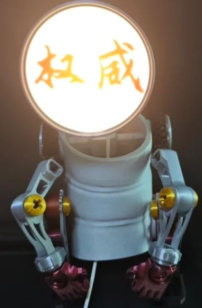
Light Assembly:
This requires some dexterity. The light panel is a thin 88 x 0.6 mm sheet, designed to precisely fit within the lampshade's recess. As shown, carefully slide the light panel into the recess along the notch, then gently press it fully into place along the edges.
Regarding the light head installation: Need some tips. The light plate is a 88*0.6 thick sheet, which is just stuck in the gap of the lampshade, as shown in the picture, snap the light plate into the gap along the notch, and then slowly press the light plate into the gap along the edges

License
You shall not share, sub-license, sell, rent, host, transfer, or distribute in any way the digital or 3D printed versions of this object, nor any other derivative work of this object in its digital or physical format (including - but not limited to - remixes of this object, and hosting on other digital platforms). The objects may not be used without permission in any way whatsoever in which you charge money, or collect fees.
Comment & Rating (2)