Search models, users, collections, and posts
Rack Mount for Beelink S12 Pro
IP Report


Print Profile(2)

0.2mm layer, 4 walls, 15% infill
Designer
4.9 h
1 plate

Right Side Cable Management Plate and Beelink
4.4 h
1 plate
Open in Bambu Studio
Boost
32
118
25
7
119
51
Released
Description
Why another rack mount for the Beelink?
TLDR: The others were just too flimsy for me. Modeling my own also gets me the features I want.
The Beelink mini PC is ~40mm tall, which leaves only 4mm spare inside the thin 1U rack slot we all want to put this into. With no side fastening options available, this is a challenge. The other models I looked at just left too much on the table. They may work, but things slip and accidents happen. I want strong.
The choices I made:
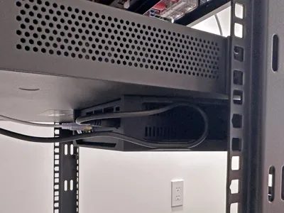
- limited front access. This model has a window to access the front panel, rather than an opening that allows the unit to slide out. This is much stronger.
- bottom tray only. This allocates all 4mm for support.
- thickness for layers. Layer adhesion is the achilles heel of 3d printing, but not so much if surface area is large. The design uses large tapered geometry.
- one piece print. The model is split in half because our printers aren't big, but I did consider splitting up the model more to optimize print direction, but this design doesn't need it.
- ribs. Steel patch panels have ribs. Most other models don't do this and flex like spaghetti. I don't get it, they are so easy to add to 3d models. Mine have them.
- M4 threaded inserts: Most other models use hex nuts, but you need:
- rear access.
- to offset the nuts further into the model which doesn't make for strong placement.
And some touches:
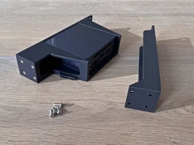
- Beelink is designed to be screwed into a VESA mount, and comes with the screws. You can fasten Beelink to my model with the same screws.
- There are also stops in the back preventing Beelink from being pushed out.
- My design adds strain relief for the power cord: a cord grip with integrated zip tie mounts. So accidentally pulling out the power cord is less likely.
Before you print:
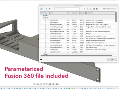
- Check the size of your M4 inserts. The holes in the model are 5.1mm. Modify > Change Parameters in Fusion 360.
STEP and Fusion 360 files included so you can make changes.
License
This user content is licensed under a
Creative Commons Attribution-Share Alike
Comment & Rating (25)