Search models, users, collections, and posts
Press Dies for Banana Pi BPI-R4 BE14 EMI Shielding
IP Report


Print Profile(1)
0.08mm layer, 4 walls, 15% infill
Designer
14 h
1 plate
Open in Bambu Studio
Boost
5
6
0
0
20
0
Released
Description
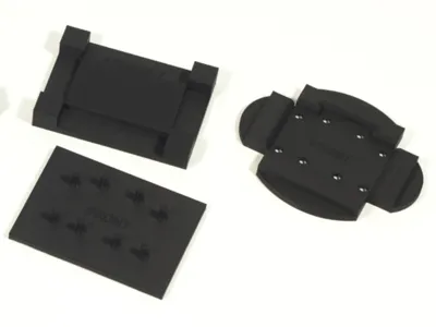
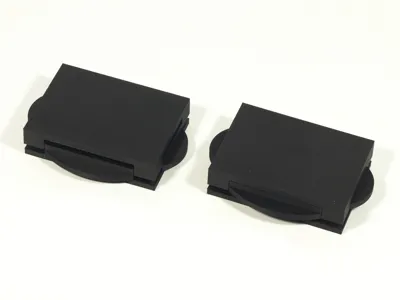
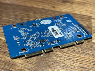
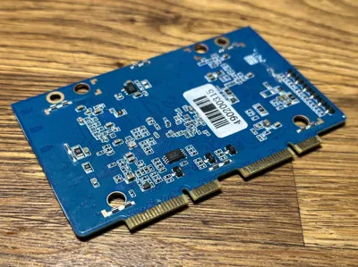
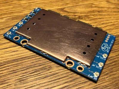
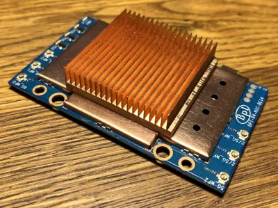
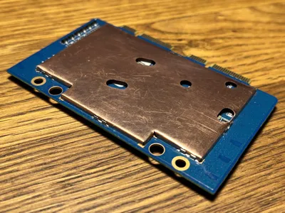
If you're using a plastic case for your Banana Pi BPI-R4 with the companion Wi-Fi card (the BE14) installed, it's a good idea to add EMI shielding to both sides of the BE14 PCB to protect it from external interference. This project provides DXF drawings for manufacturing EMI shield blanks from sheet metal and a 3D-printable die set for pressing the blanks into can shapes suitable for installation with shield can clips. The top-side shield can will make cooling the ICs easier, too.
Bill of materials
- 0.2 mm sheet metal (preferably copper).
- 16 × Harwin S0961-46R shield can clips—optional, but highly recommended. Buy a few extras as spares.
- Thermal pads for the BE14 board. The intended z-clearance between the ICs and the shield can is 0.9 and 1.1 mm, but it may vary depending on the quality of the shield blanks.
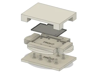
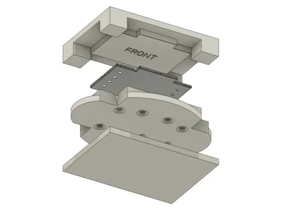
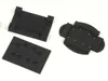
How to use the die set
- Place the blank on the inner die so that it is located between the four corner studs. Make sure the blank is facing the correct side down (the outline is not symmetrical).
- Place the outer die on top of the inner die and press it all the way down. You can use a vise or just step on it.
- The intended method for extracting the pressed part is to insert the extractor tool into the openings of the outer die and apply equal pressure to the side tabs. However, depending on the blank’s quality, it may catch on the inner corners and come out warped. To prevent that, manually remove the inner die instead.
- Either way, you'll end up with the part still attached to the die. Carefully pry it out with a sharp tool. If the blank was laser-cut, the tiny side holes will help with this.
Manufacturing tips
- Laser-cutting is recommended for shield can blanks. Although, you might want to practice die-pressing with hand-cut samples first.
- If you’re cutting the blanks by hand, make sure to include the openings on the shield can facing the main board of the BPI-R4. These are necessary for the can to clear the tall SMD components on the main board.
- Have some spare shield blanks in case the first pressing doesn't go well.
- After 3D-printing, knock down the layer lines on the outer die using 1000-grit sandpaper. Don't overdo it, though, and don't sand the inner die.
- Lubricate the dies with grease or oil for easier pressing and part removal.
Installing the shield can clips
- While you can solder the shield cans directly to the PCB, doing so is difficult due to the added thermal mass and may risk overheating the board.
- Before installing the shield can clips, inspect the solder pad layout on the PCB to figure out their intended positions. Use the shield cans as a guide.
- Solder paste is recommended over regular solder wire. Apply a small amount to the soldering pads (see picture).
- Put the clips onto the soldering pads. The alignment doesn't have to be perfect at this stage.
- If available, use a preheater to bring the PCB temperature to ~100 °C.
- Set your hot air soldering station to 350 °C with minimal airflow.
- Align the nozzle vertically over the clip and very slowly bring it down from ~50 mm above. When the solder begins to flow, the clip will self-align to the pad.
- Repeat for the rest of the clips on one side, then move on to the other side of the PCB.
Installing the shield cans
- If you used hand-cut blanks, it is recommended to insulate the cans on the inside (and on the outside, too, for the can facing the main board) to prevent shorts. Avoid insulating the walls, which the clips latch on to.
- Measure the internal height of the top shield can (depending on the quality of the blanks, it may differ from the design value). Apply thermal pads of the appropriate thickness to the ICs. The height of the ICs is 0.9–1.1 mm, but you'll have to factor in ~0.3 mm for compression.
- The can may not align to the clips perfectly and require some fiddling to get installed. In case of gross misalignment, you might have to re-solder some of the clips.
- Lightly press the board between two flat surfaces to push the shield cans all the way into the clips.
Disclaimer
Modding the BE14 card will void the warranty and may cause damage to it or the main board of the BPI-R4 router. The author of this project bears no responsibility for any damage or malfunction resulting from this modification.
License
This user content is licensed under a
Creative Commons Attribution-Noncommercial-Share Alike
Comment & Rating (0)