B85D-V2 Motherboard Case


Print Profile(1)

Description
Boost Me (for free)
If this model meets with your approval, esteemed creators, might I humbly request your support? Even a positive review would be fantastic!
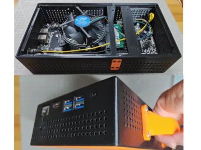
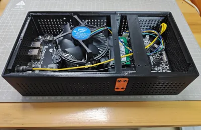
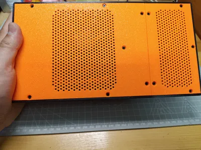
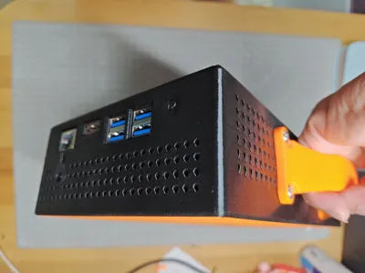
A case specifically designed for the B85D-V2 motherboard. Minimizing size wasn't the primary goal; it utilizes the original CPU heatsink, and aside from height, other dimensions are snug with minimal wasted space.
Note 1: Some anti-print-warping design elements necessitate heatsink removal during motherboard installation.
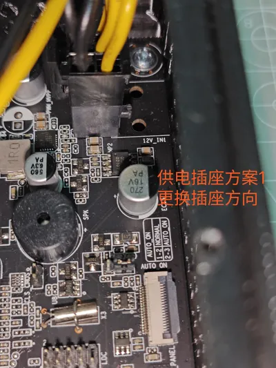
Note 2: The case doesn't provide space for the 6-pin motherboard power connector to avoid wasted space. However, I have three solutions.
1. Remove the 6-pin power connector, straighten the solder pins, re-solder it vertically to the motherboard, and trim excess (this is the method I used).
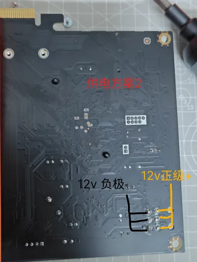
2. Without modifying the connector, solder the positive and negative wires from the power supply directly to the connector pins on the back of the motherboard (a diagram is provided in the showcase section).
3. I've also pre-cut openings at the connector's location; if all else fails, use a craft knife.
Accessories: One DC-to-6-pin power cable, four motherboard screws, two M2x5mm screws, twenty-seven M3x4mm screws, four M5x8mm screws (for handle, 4mm nut combination can be substituted).
Detailed installation steps are as follows:
1. Inspect the motherboard, choose a power connector solution, modify the motherboard accordingly, and remove the CPU heatsink.
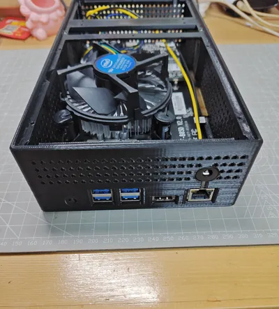
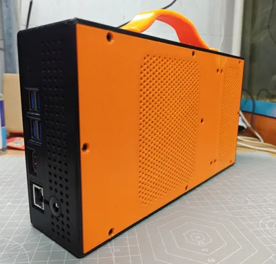
2. Secure the larger left chassis main body to the three rectangular mounting strips with screws; cut the small crossbar between the network port and the DC power mounting hole, then install the DC power connector.
3. Slide the motherboard into the mounting slot from the bottom of the left chassis, align with the holes, and secure with two motherboard screws.
4. Insert the right chassis main body, aligning with the left chassis, then fasten all the chassis main body connecting strip screws, and finally tighten the right motherboard screws.
5. Install the heatsink, check other motherboard interfaces, attach the handle, and install the chassis cover. From step 5 onwards, do whatever you like; it doesn't really matter.
License
You shall not share, sub-license, sell, rent, host, transfer, or distribute in any way the digital or 3D printed versions of this object, nor any other derivative work of this object in its digital or physical format (including - but not limited to - remixes of this object, and hosting on other digital platforms). The objects may not be used without permission in any way whatsoever in which you charge money, or collect fees.
Comment & Rating (2)